AN/URT-23B (Big Momma)
Radio transmitting set, 2-30 MHz, 280000 channels,
1 KW, AM/CW/USB/LSB/FSK
Major components:
T-827G Transmitter, Radio - aka Harris RF-131?
AM-3924B Amplifier, RF - aka Harris RF-110
PP-3916B Power Supply - aka Harris RF-124
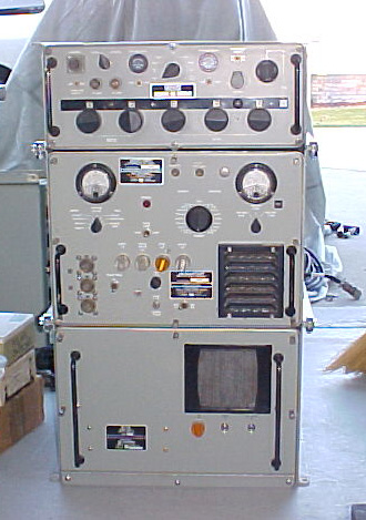
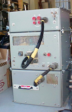
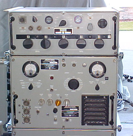
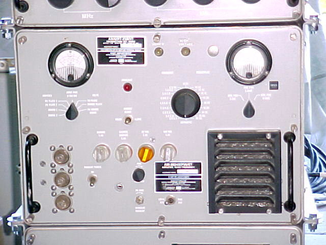
The whole unit, front & back, and just the exciter and amplifier (power supply is the bottom unit)
The power supply I now have here is 230 volt single phase, the RF-124. It weighs 200 lbs. I do have the 3-ph supply, it's smaller, may be a little lighter, but of no use.
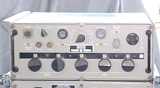

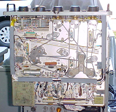
T-827G, the exciter, front, top, bottom
T-827G - It was originally developed in 1961 by the U.S. Navy for the Radio Sets AN/WRC-1, Transmitters AN/URT-23( ) and AN/URT-24 .. it is the
exciter T-827( ) /URC unit of these equipment's. USAF purchased units and
re-nomenclatured them and in some silos they were painted black for some reason. Developed and originally produced by General Dynamics, Rochester NY.
The AN/URT-23( ) is still in use today!!!!
the above info thanks to:
Fred Chapman, W4CHT

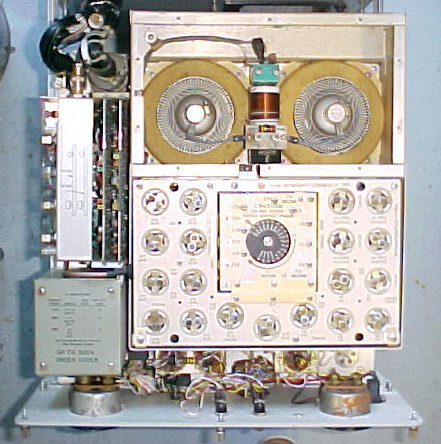

AM-3924B, the amplifier, front, top, bottom, close up of the final cage uncovered.
All shown as initially stacked in the shop on 10/22/03 for closer inspection, checkout of primary power links, etc.
First time on the air - Nov. 9, 2003, on the Vintage Sideband Net, 14.292mc, paired with an R-390A receiver.
I'd been working on it for over 2 weeks, didn't get much info on the exciter until a week ago a fellow sent me 3 .jpg files of the general schematic, and then at the end of the week I received loaner manuals. Had relatively minor problems to get it on CW into the dummy load (which gets hot quick), but took a little longer to get the audio figured out.
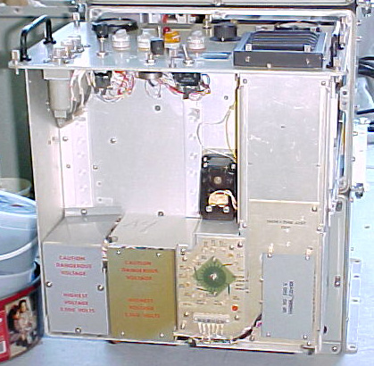
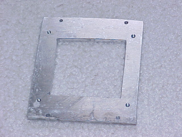
The cooling fan is a Rotron ~4" fan, run on 120vac, 400cy. It turns at 11,000+ rpm, and puts out a real scream. I have had info from 2 other owners who have said the same, and who recommended finding a quieter replacement. I fabricated a mounting plate for a centrifugal blower similar to another installation.
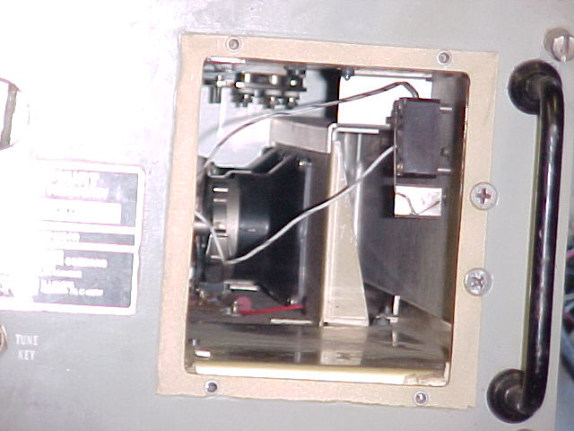


As an engineer, I made air flow and temperature measurements in & out, before and after. The new flow was within 5% of the original, and I felt that in ICAS it would be sufficient. Then I was advised by an ex-Harris engineer to not modify the cooling system, but to change the bearings in the original fan to reduce the noise. Looking into the opening, you can see the driver tubes mounted in what seems as the middle of the flow path, after the fan & it's 2mf capacitor were removed. The "muffin" fan's circular motion spreads the air flow heavily on the sides of the compartment, and the capacitor, mounted on the left wall, originally directed flow to the right side and under the driver tubes. The centrifugal blower directs the flow largely toward the top of the chamber, and even tho' it's flow was the same, it would not trip the flow switch (it's visible in pic #2 above) which is mounted on the right side wall when mounted as shown. I rotated the blower 90 deg. clockwise to direct the flow to the right. The flow pattern was carefully selected by the designers for proper cooling of all the tubes, plus the coil assemblies. I have disassembled the Rotron fan and am awaiting replacement bearings. I will only use the rig intermittently in SSB operation until I re-install the Rotron. The final tubes dissipate about 1kw while just idling in SSB mode, so heat is a major issue. I look forward to a warm shop this Winter.
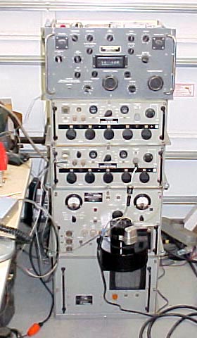
The "tall stack" with the R-390A receiver on top, and an extra exciter which needs some work & is there to make cabling to it easier when I'm ready to work on it. This arrangement is what I've had on the air several times since the first contact on Nov. 9.
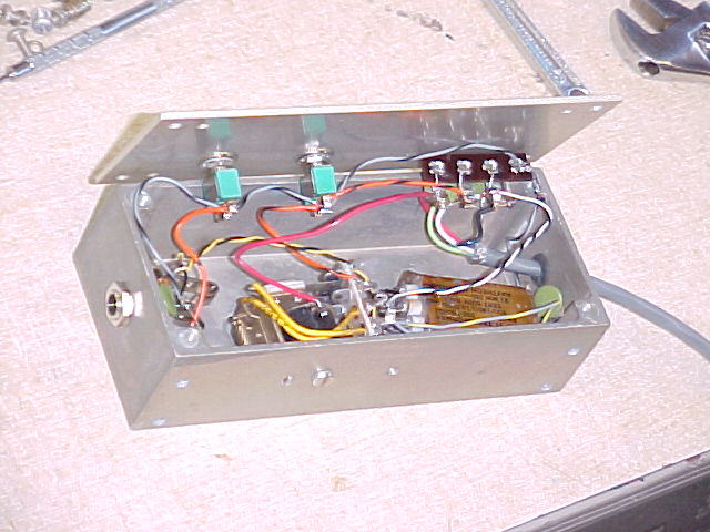
External box for a microphone transformer and relay to allow a "std" mike with 1/4" stereo phone plug to be used. The transformer changes the high impedance mike output to the 200 ohm exciter input impedance. The relay allows the PTT switch in the mike to switch 12vdc to the PTT line. The relay also provides a normally open and a normally closed line to ground, which can be used for muting a receiver, etc.
Dec. 1, 2003
After reports of a 120cps "hum" on the signal, the following was found:
 first data
 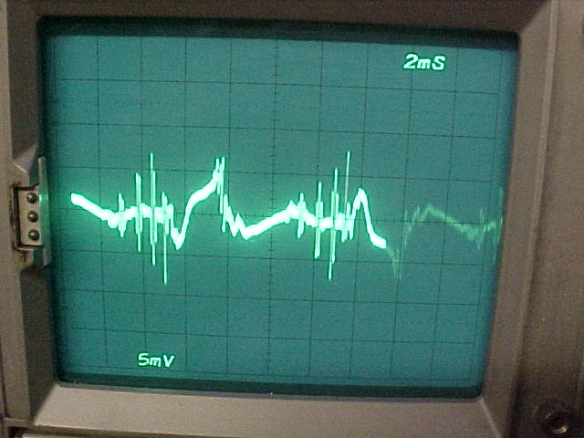 second data
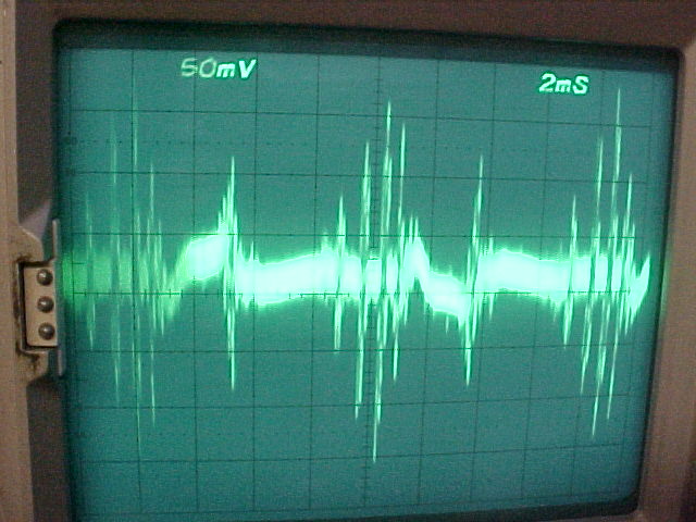
First data shows trace of exciter output with PTT off and amplifier HV off. Hash occurring at 120cps repetition, about 250mv p-p. This hash will modulate the exciter when PTT is on, even with mike not on.
 first data
 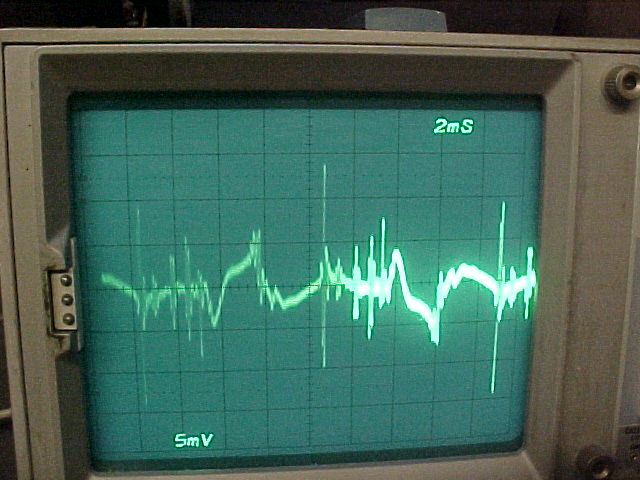 second data
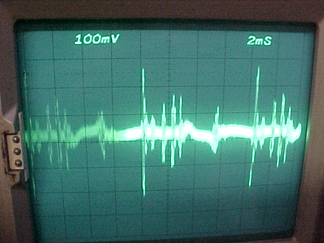
(note different vertical scale, 100mv/cm vs 50 in upper pic)
First data again, same signal, with amplifier HV on. Note the additional ~500mv p-p
single spike at 120 cps.
NOTE: Second data - The above is a good example of not checking why something's intermittent. The left pix & the text was using a scope probe with a lousy ground lead. When resolved, as shown in the pix on the right, the hash is about 15mv p-p and the spike about 25. There is still a problem, but the levels are a lot less (about 80% less) than previously thought.
I'll have to get into the exciter power supply to solve this, it appears. The effect on the signal varies by output frequency, and it seems to be worse when the SWR of the feedline is high, although the signal being modulated by the hash only, is at a low level, less than 50 watts output, so there should not be very much RF "floating around." Bypassing everything in the external microphone wiring cured problems there, so perhaps there's more bypassing to be done in the external lines.


Your set looks like an early version of what Harris sold as the RF-130 transmitter. Harris used to be RF Communications.
I don't recognize the exciter you have. Later versions used the RF-131 exciter and the same RF-110 amplifier that you have. Yes,
the amplifier has a pair of 8122 drivers and the finals are
4CX1500Bs. The nominal exciter output is 100 milliwatts.
Even later versions used the Harris RF-1310 or the RF-1310A exciters. The RF-1310H is a frequency hopping exciter that works
with this system. There's also a very nice RF-601 automatic antenna tuner.
Also you may have a non-Harris unit. They were made by Stewart Warner and other
contractors
the above info thanks to:
Bill, W8FIX 9/03
=============
The battleship USS Missouri has one
http://www.kh6bb.org/photos.html
I've just been alerted (12/04/03) to the following great page on the
amplifier, take a look at what N2BC has done with his RF-110A:
http://home.stny.rr.com/n2bc/Harris_RF-110A.htm
a "google" search on URT-23 will reveal much more info
Radio to home page
comments to anchor@ec.rr.com
And remember: "They don't make tubes nowadays like they used to..."
this page was last revised on 12/22/2005
T-827 exciter info
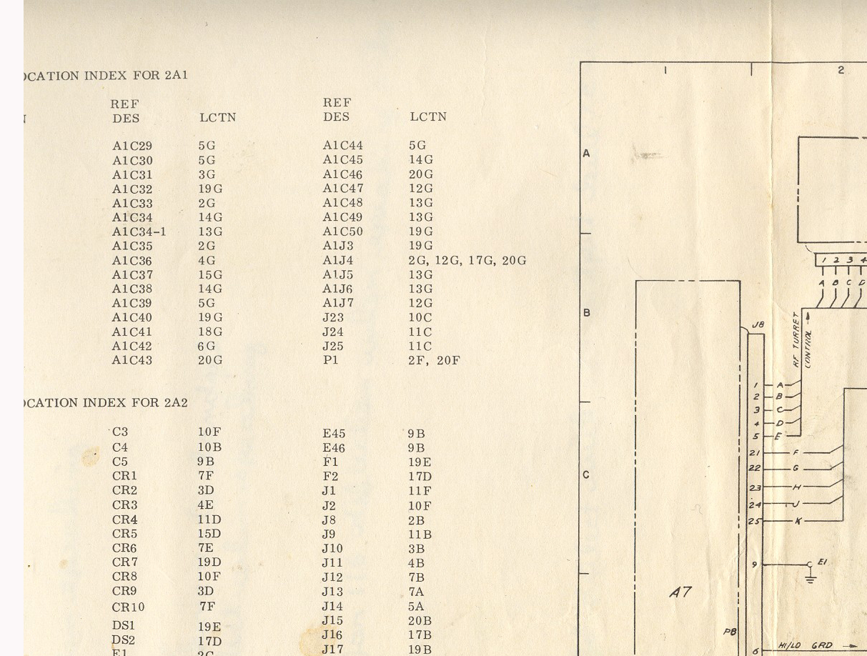
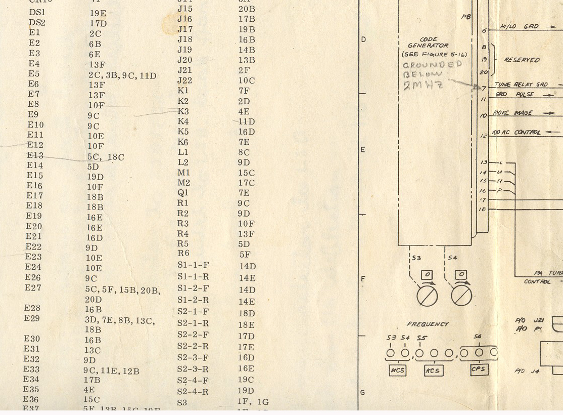
Here are blowups of the interconnection diagram that I got from John S., Nov. '03, for the early version T-827 exciter
part 1, right side (each file overlaps the adjacent ones) I opened these with Adobe Photoshop, and printed each, using 170% scale, they each filled an 8-1/2x11 sheet, and were all the same scale. 12 pages, can be pasted together for one WIDE sheet.
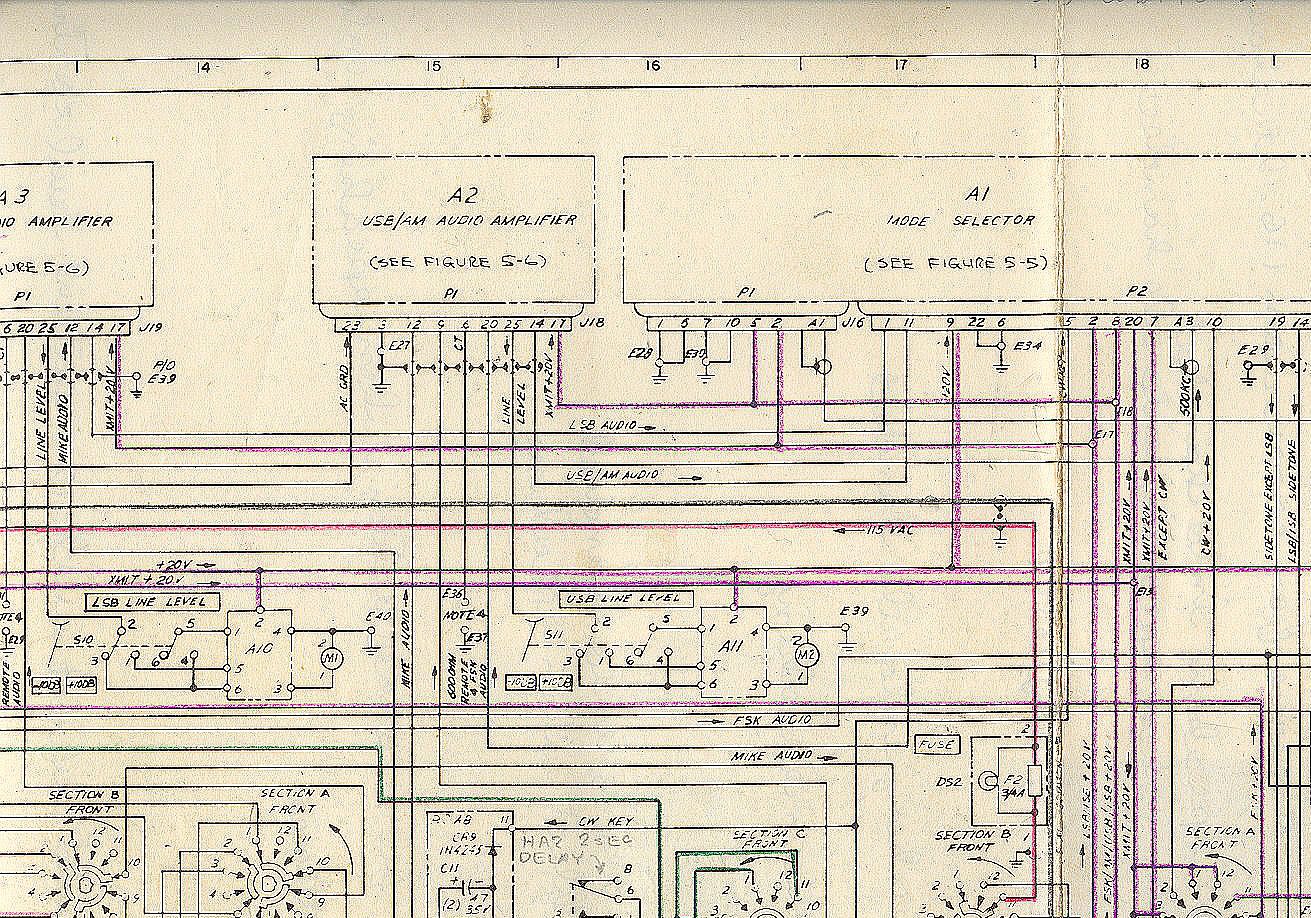
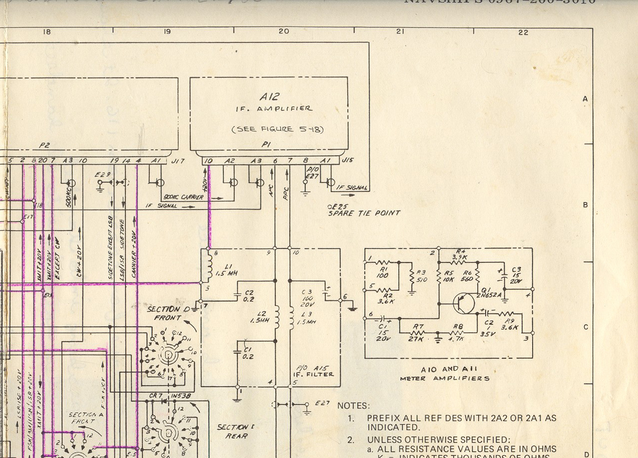
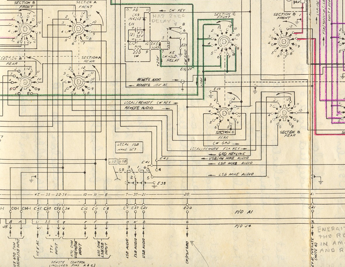
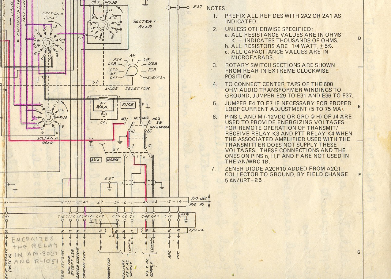
Part 2, center

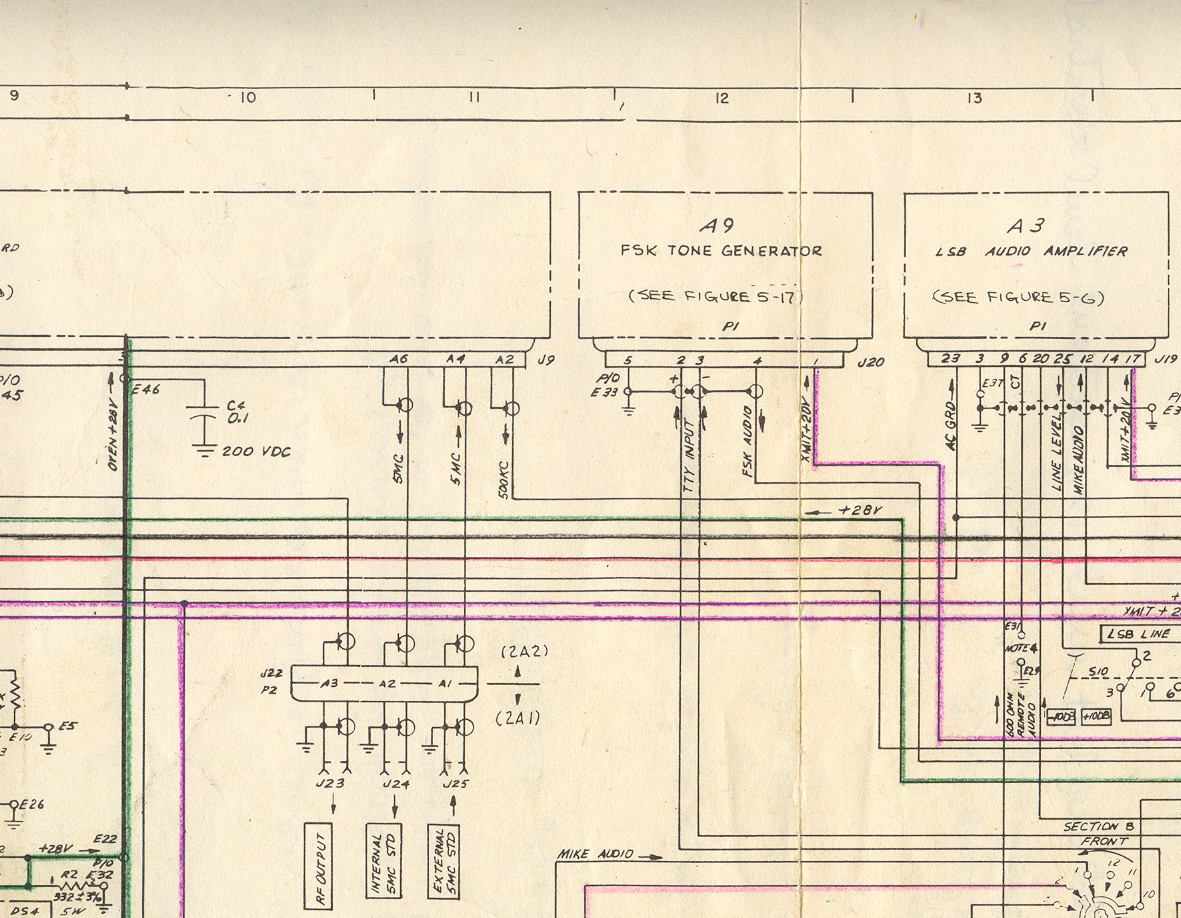
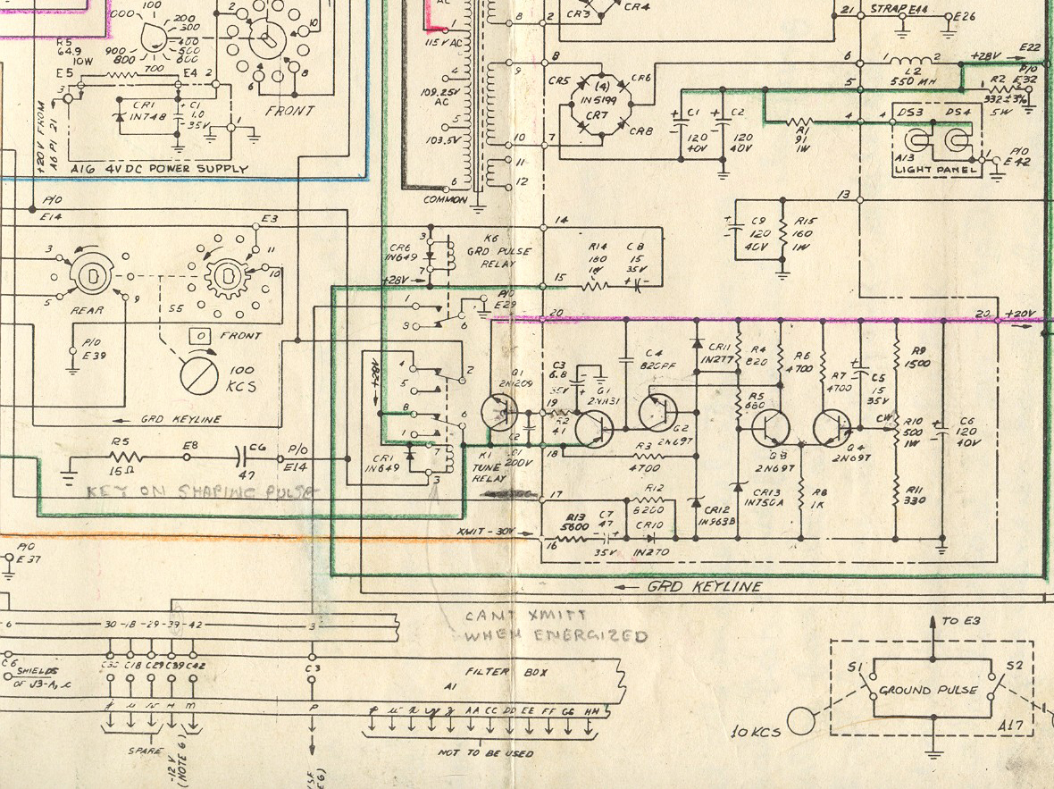
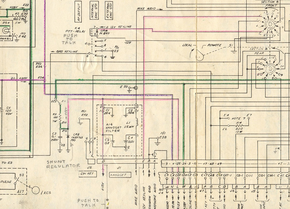
Part 3, left side

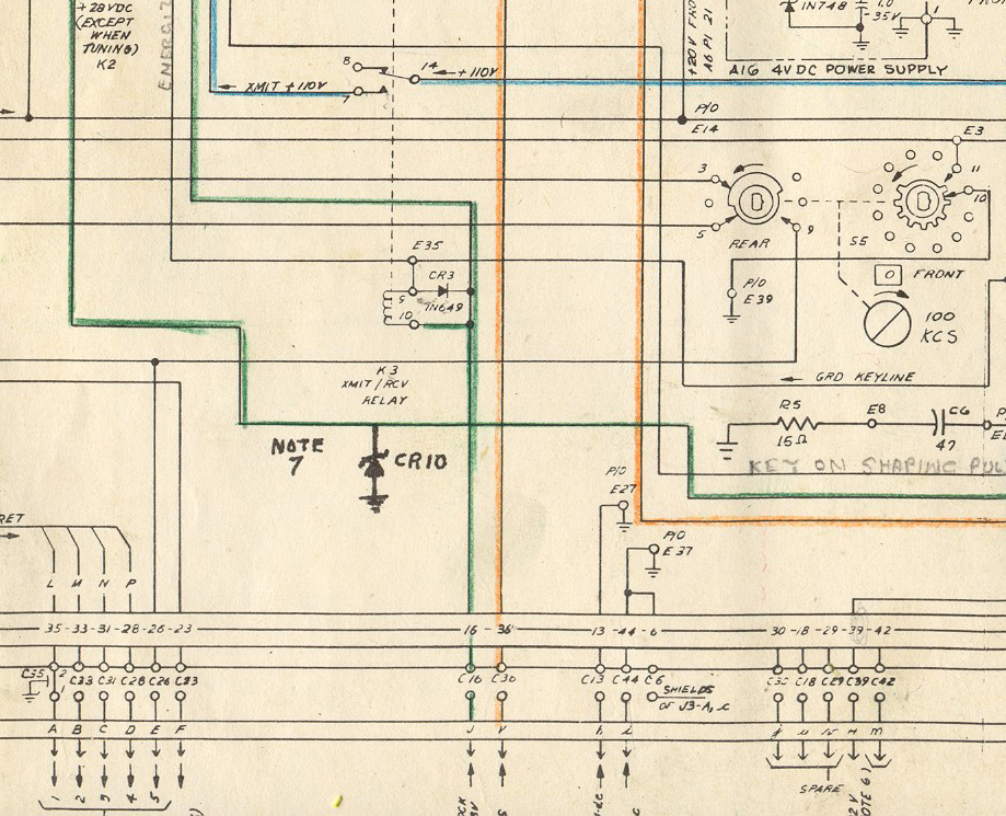
Interlock diagram (swampy & i are trying to get our exciters operating separately from the amp, April, 2004)
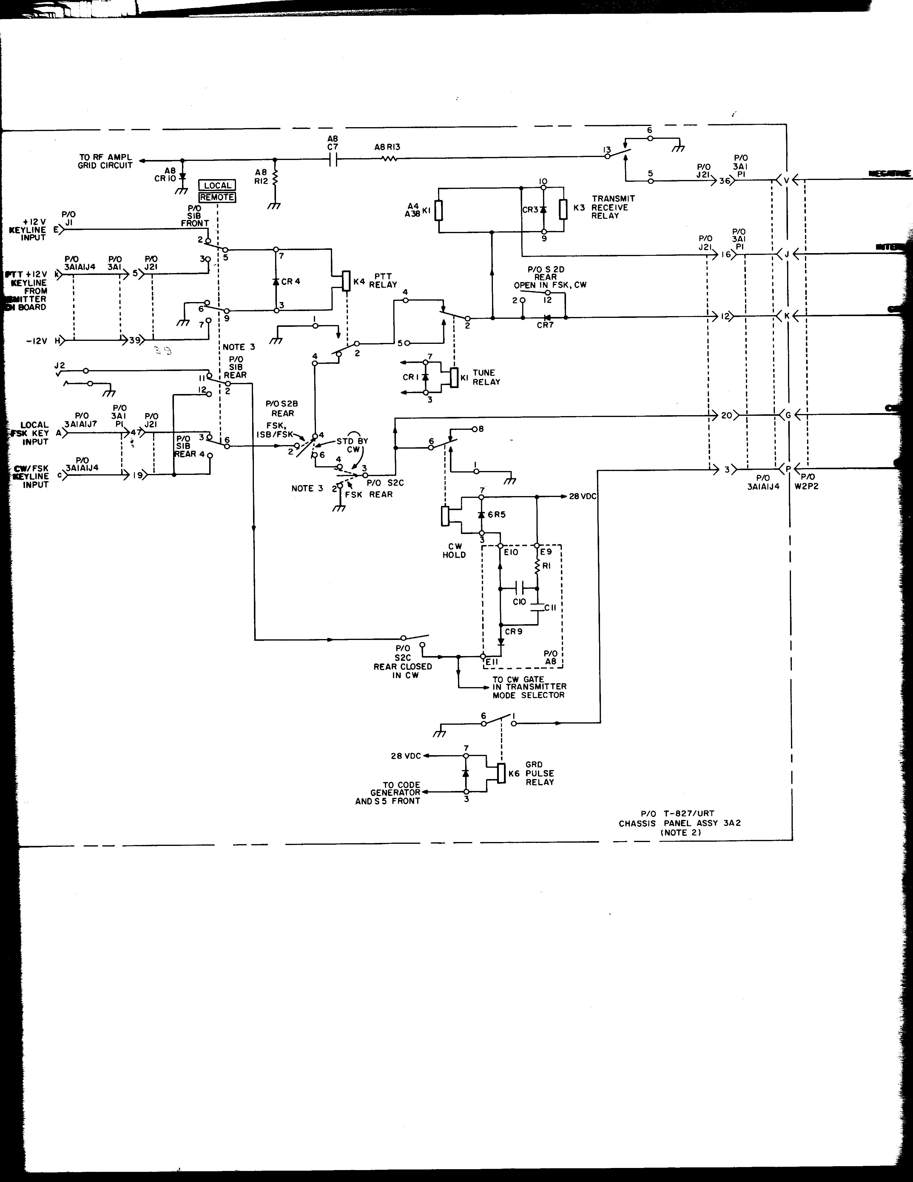
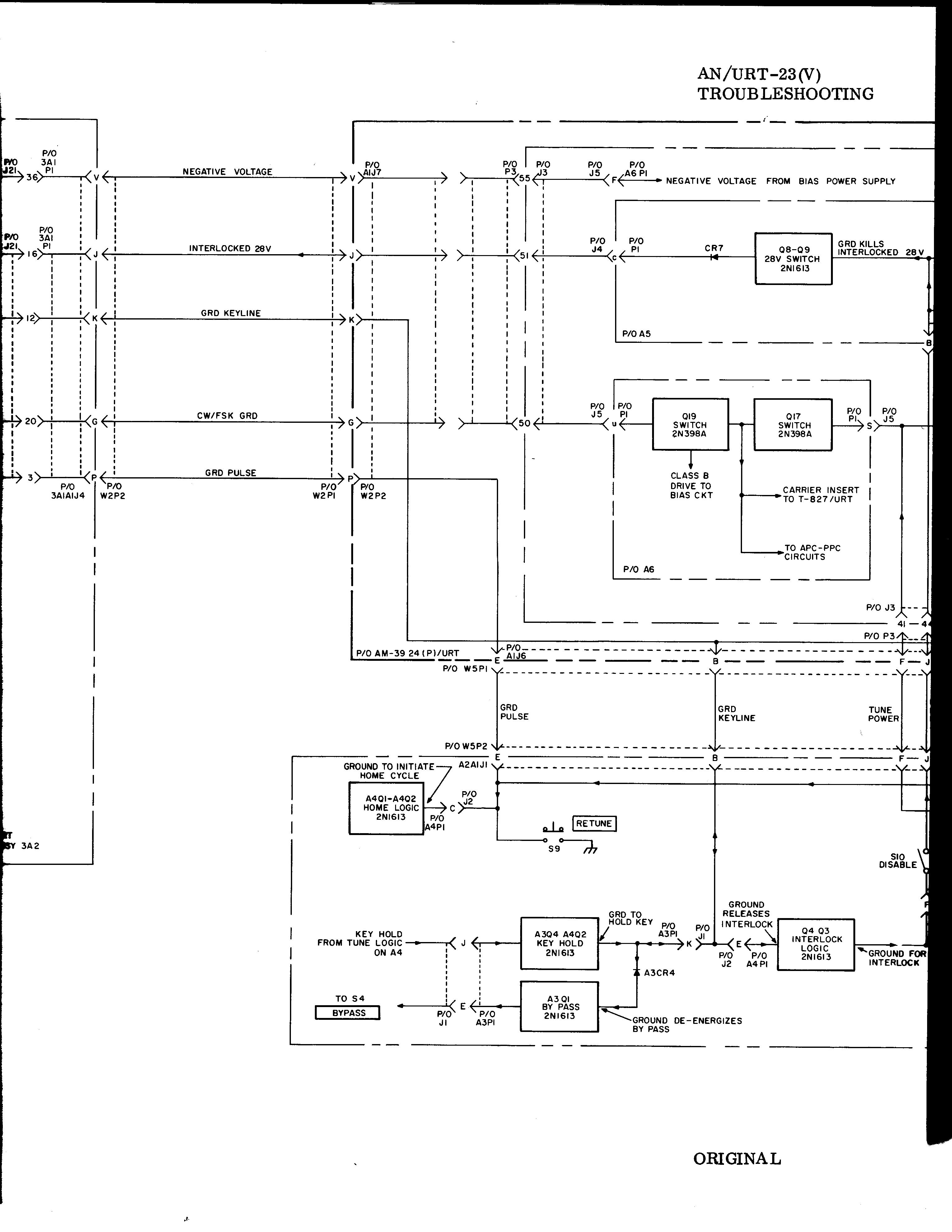
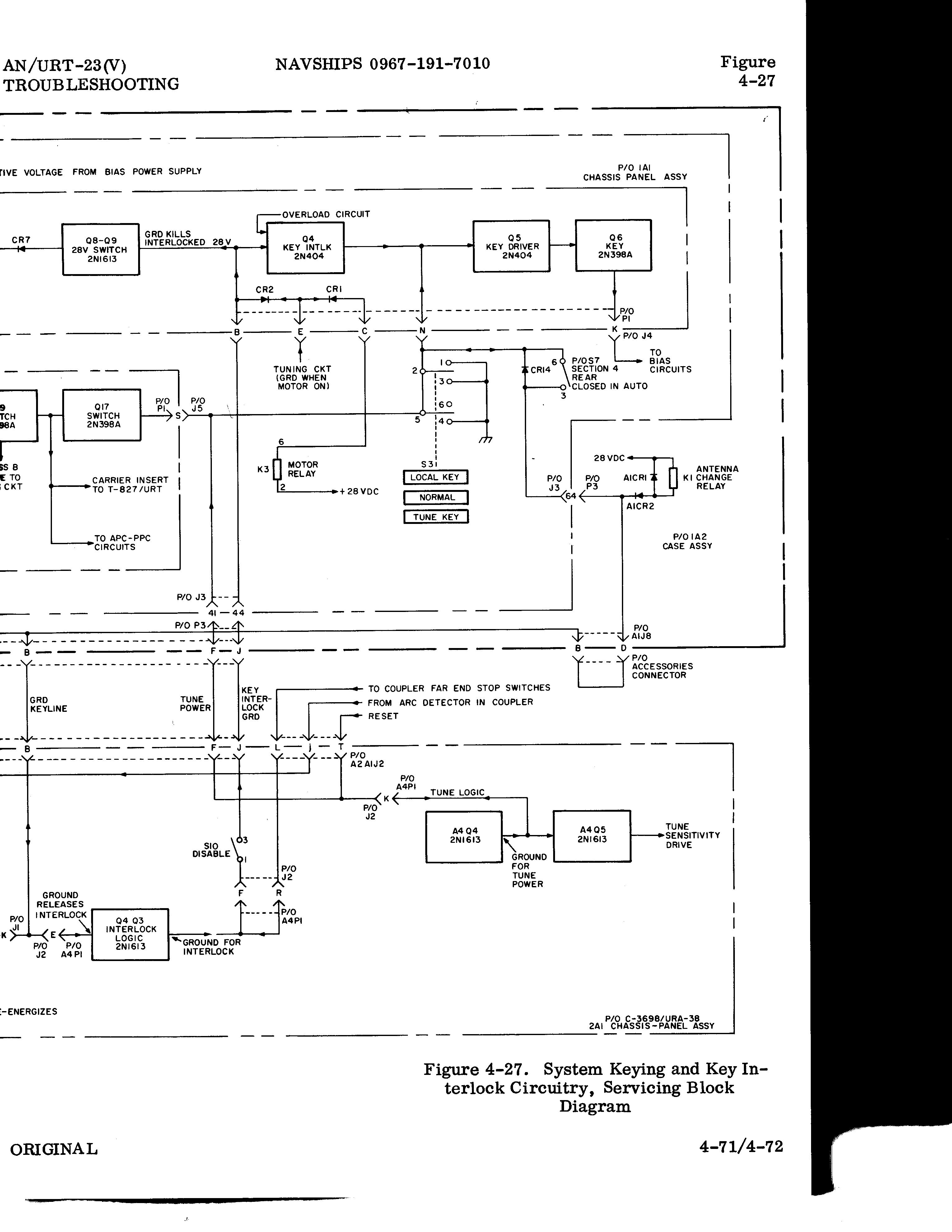
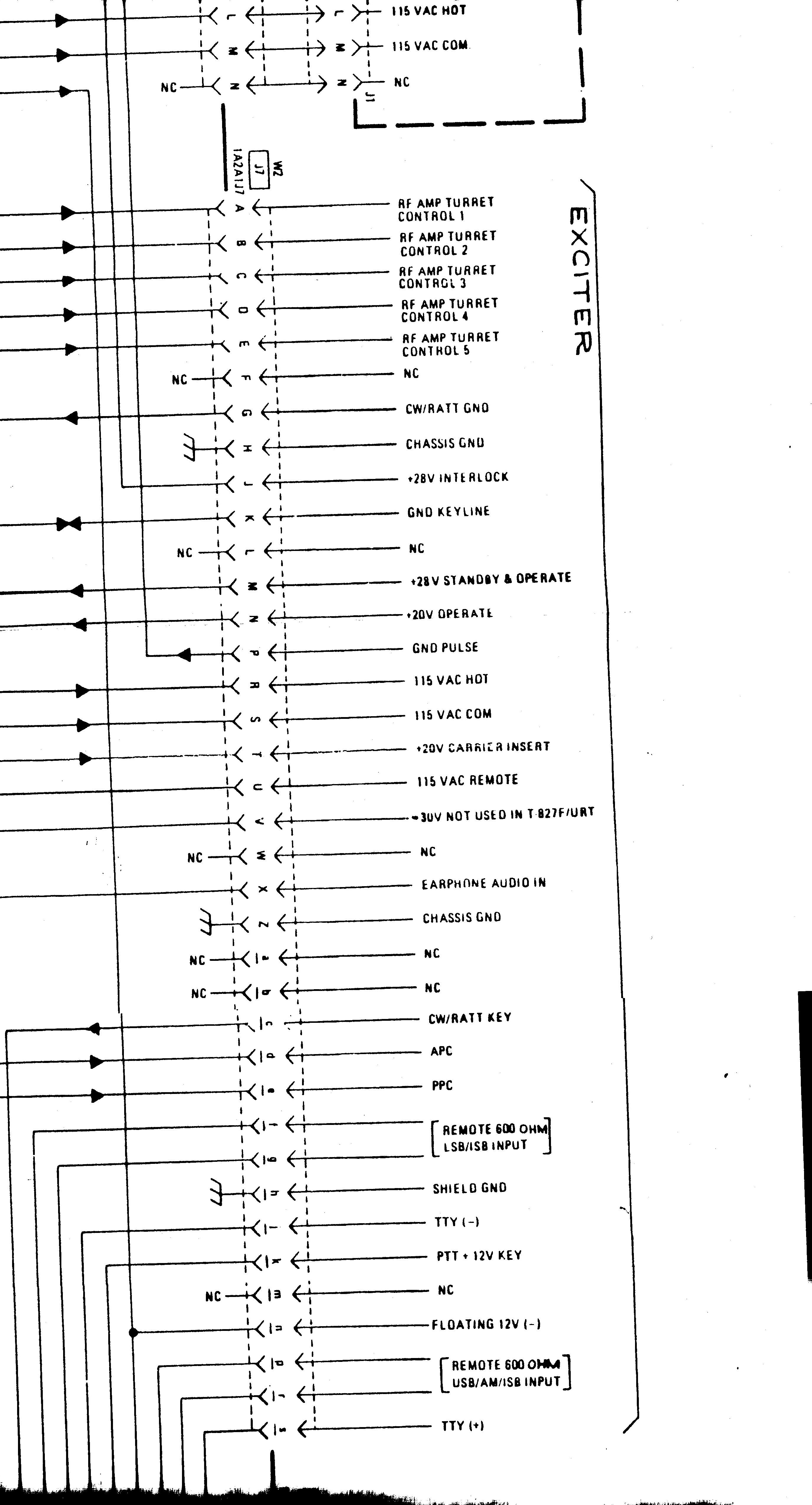 Connector J-4 on the exciter, J-7 on the amp


J-4
J-4
w/ext. con.
P-4, mating unit
pinout is opp. hand from J-4
Radio to see home page
comments to anchor@ec.rr.com
And remember: "They don't make tubes nowadays like they used to..."