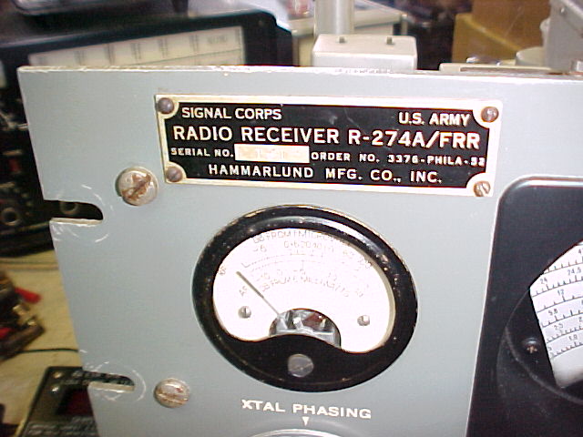
SP-600-JX-1 s/n 4706 R-274A/URR s/n 1613
Initial inspection, 3/7/05
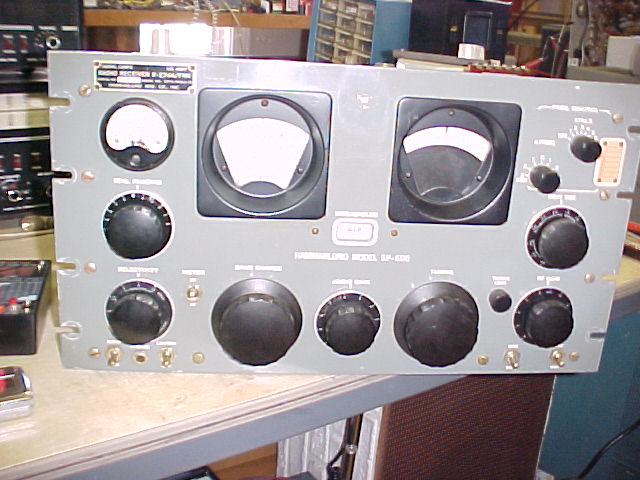
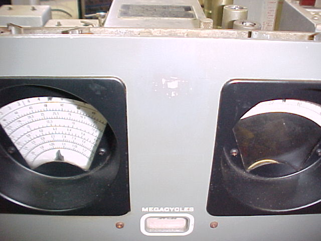
The front panel is in good condition, just small "moons" at the rack mount screw holes. There is a top cover, not shown. All original knobs and switches, a small paint scrape at top center, may be where a tag had been glued, as the paint has been "polished" there. Small scrape above the xtal switch. The bezels' paint is very nice. The dials are bright white, but there is some widening of the lines and numbers in some areas, particularly for the highest band, maybe some slight corrosion.
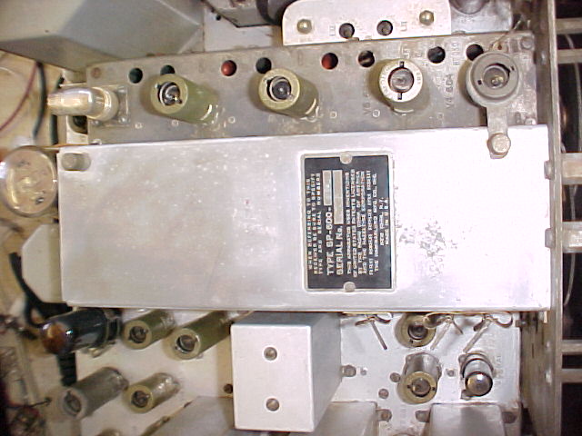
The chassis is generally dirty, but no major corrosion and should clean up very well. The IF cans are have a normal matte appearance, no pitting or discoloration. They could be left as is after cleaning, or polished to be shiny. The right side dial lamps are missing, as is the wiring for all lamps. There is no wiring to the meter, the small terminal strip that mounts to the terminals is missing. The wires have been cut off close to the meter switch. The orig. 3 allen wrench keys are in place, only 2 tube shields are missing. The "hose clamp" style clamps are in place for the 6V6, 5R4Gy and the FCU's 6AC7, and the HF osc. 6C4 has it's proper shield with hold down tab. There's a rt angle coax fitting on the ant. conn. All tuning hole plugs are missing. All xtal hold-down fingers are intact on the FCU. One of the filter chokes has an open hole, it looks like the original solder to close it has been removed with a torch. The whole choke has been very hot, all the paint is peeling. The top of the RF deck cover has previously been polished, but not protected with a clear coat and is not uniformly shiny. (There's a similar area on the left side panel.)

The bottom cover for the RF deck is in place. There is an 11-51 date on all bathtub caps, and 1-52 on the filter cap, so this radio was probably manufactured in Jan. or Feb. 1952. The 3 sections of the filter cap have an ESR of 1.9, 2.0 and 2.1 ohms, marginal. Several extra wires are in evidence, e.g. an orange one from pin 15, (6vac) on the pwr xfmr, to pin 3, (fil.) on V-7, the IF gate. Pin 6 (screen) of V-10 (2nd IF) is connected thru an orange wire to the voltage dropping resistors in the p.s. area. A couple of wires are new, and/or have been moved in the filter cap & terminal strip area. There's a typewritten tag on the filter cap that says, "The B+ has been removed from the xtal osc. can." Many "BBOD's" are split. There are 2 leads, cut and taped, hanging from the ctr secn of the meter switch, they should go to the meter. Pin 3 (fil) of V-7 (IF gate) has a taped wire hanging from it, probably the dial lamp lead. The 5 10mf@100v bathtub caps all have high ESR, from about 3 to well over 20 ohms. They all should be well below 3, and must be replaced. The bathtub cans can be "re-stuffed" if desired. A wire from terminal 1 of the power xfmr is cut and hanging loose, it should go to the AC power switch. There is a similar cut wire hanging loose in the area, but it doesn't go to the switch. It does go into the wiring harness - the lacing on the harness has been removed for most of its length, see the HFO area for another hanging wire which may be related, and a replacement orange wire.. The dial drive slips badly, its wheels are dirty and tarnished, as are the band change gears.
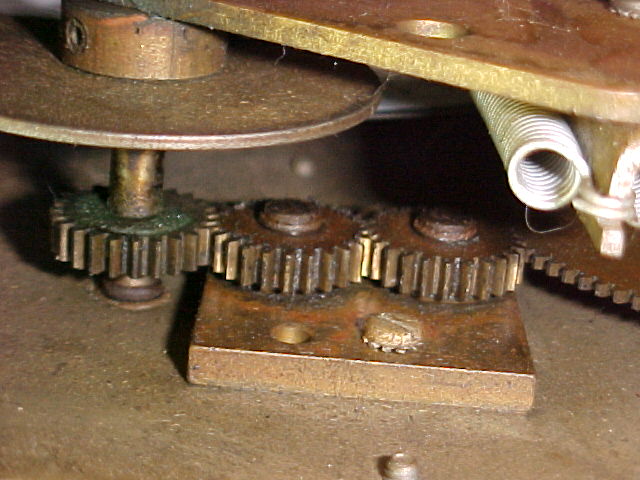

They can be cleaned quite well without removing the front panel (but not polished).
The AC line bypass caps have been broken open (probably when under power, as evidenced by the scorched area of the chassis) and disconnected.
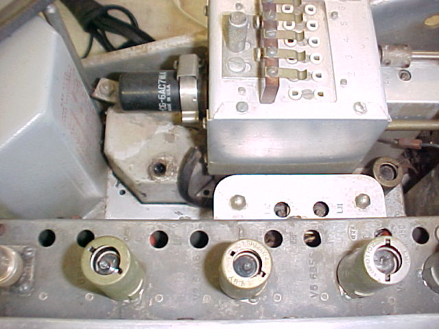
Observations during disassembly for cleaning, 3/15/05

The RF deck has been re-capped, new "orange drop" style replacements are visible thru the access holes and from the tuning cap compartment. The FCU xtal unit has been removed, it's wires have been removed/replaced, can we assume it has been re-capped? (probably, see further.)
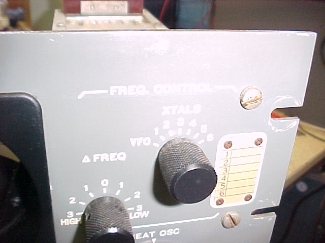
The 3.5mc Osc. has been recapped, as have 2 of the 3 IF cans, so perhaps the FCU was done. It's B+ has been removed, so it's inoperable, but it may be operable if the B+ wire is located and re-connected. It's only used for fixed freq. operation, with the proper xtals.
The IF can covers have now been removed, as have knobs and the RF tuning cover. I was preparing to remove the FCU for re-work and access to the BFO can, but held off when it was evident that it has been removed in the past. It will be necessary to remove it to determine if the "pod" IF coupling section has had it's caps replaced, and to inspect the BFO can.
Time required for service will be reduced due to the prior recap work in the RF deck & 3.5mc Osc., and possibly the FCU.
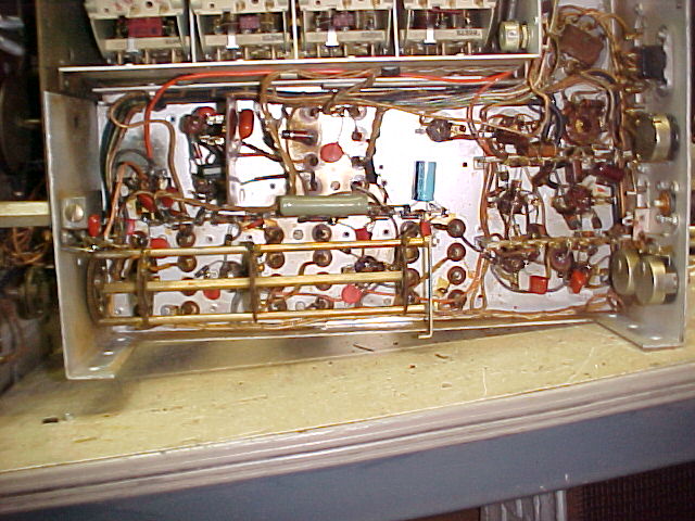
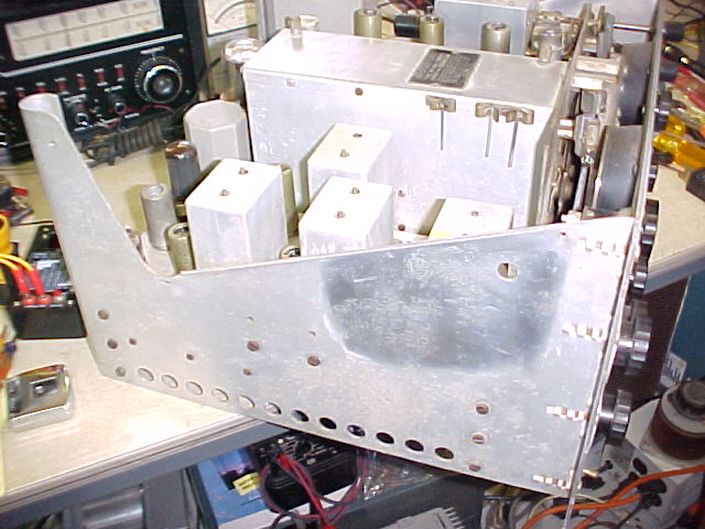
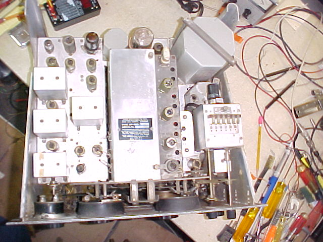
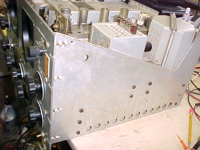
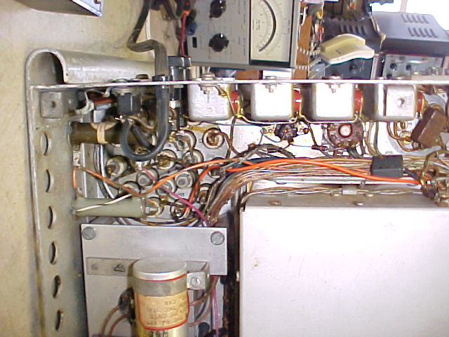
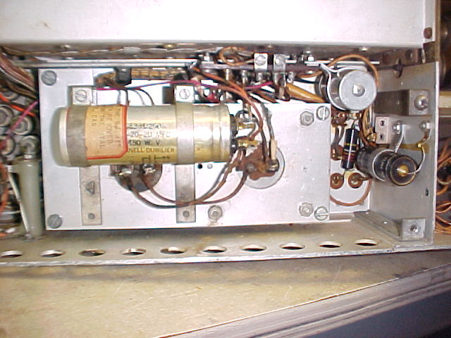
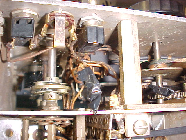
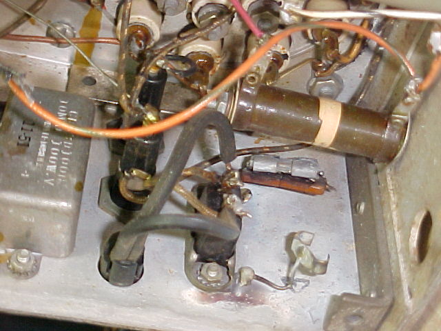
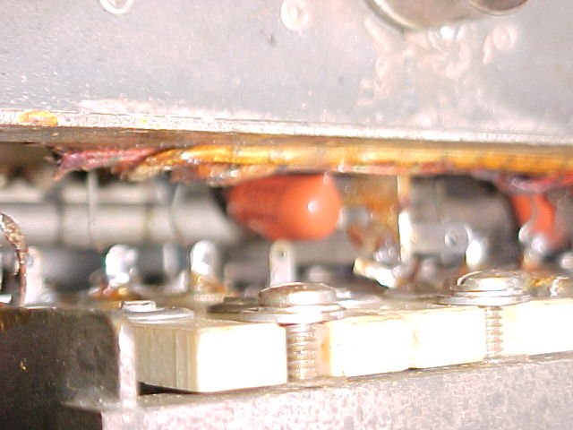
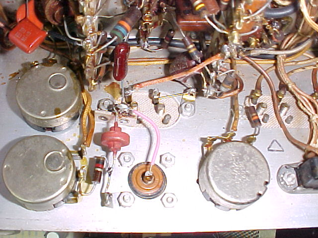
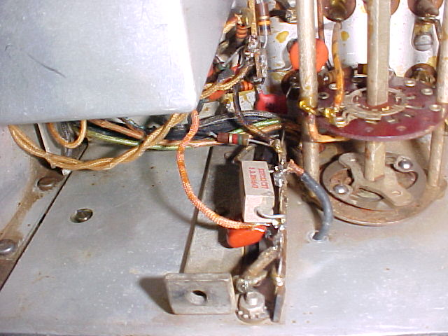
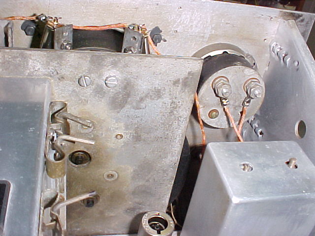
3 pix - the left side recapped, and the E-13 terminal strip
area replacements
for the "bathtubs"
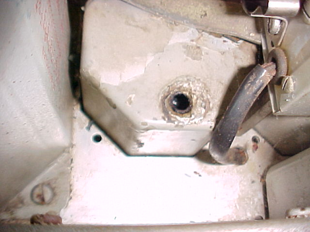
The left side has been re-capped, the 4 bathtubs on that side have been replaced, the filter capacitor & chokes have been removed to allow access to E-13 and it's 1 BBOD and the "pod." The filter choke with the hole in it has been isolated and checked with a megger, showing a resistance from the winding to ground of over 1000 megohms at 750 vdc. it apparently has not been damaged, but the reason for the paint peeling and the hole in the top of it is still a mystery.
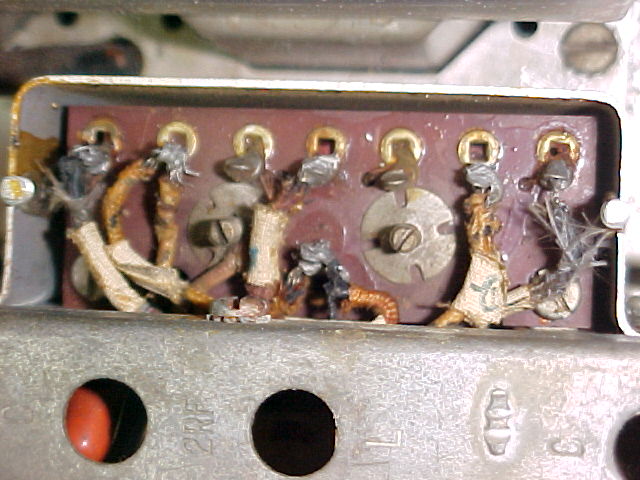
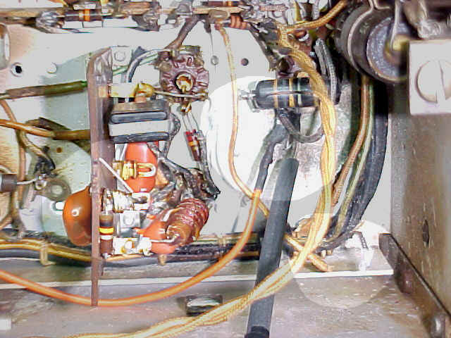
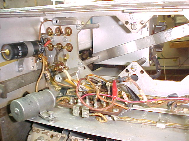
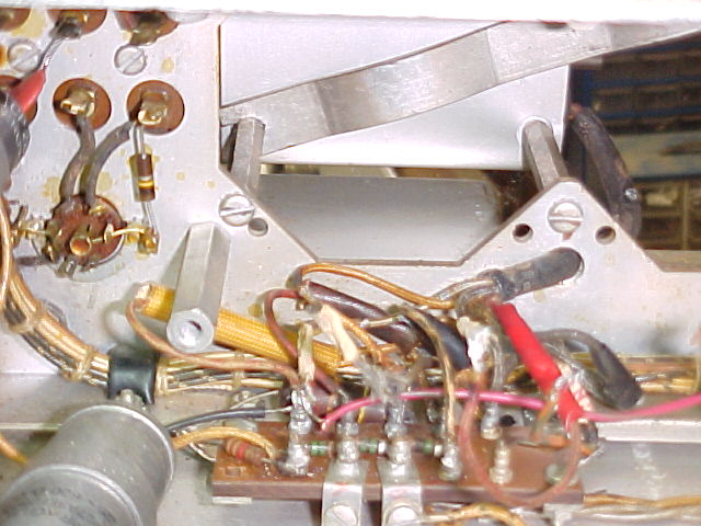
The ratsnest at E-13 terminal strip can be seen. The cable coming thru the hole in the chassis is from the FCU, which is still in place on the pix. E-13 is a main junction point for the FCU and some other connections. One wire from the FCU was hanging loose, one was on a terminal but not soldered, and the B+ line was connected before I removed it from the choke terminal. The filter chokes have been wire brushed and repainted, after filling the hole in one with soldered pc of sheet brass, the whole rcvr has now been cleaned, and almost ready for re-assembly. Only the modules in the turret remain to be recapped, approx. a 1 hr job..
The FCU was removed and the cover opened to reveal that it had been recapped previously, so it was closed and re-installed.
The turret modules are now recapped, the wiring mess at E-13 has taken hours to resolve, and now all is proper. Previously the FCU and RF deck areas that must be switched in and out for proper operation weren't switching properly, and 240vdc was on sections that should have 150vdc regulated. The FCU has been tested and works as it should.
Neither the IF out jack or the phono jack were connected, they have been properly connected.
IF alignment wasn't too far off, the 455kc section was better than the 3955kc secn. AVC action was poor, it acted like the AVC line was abt 100k to ground, which it was. Turned out that main problem was a mica cap in the xtal phasing can which was abt 70k ohms to gnd. The AVC/Man switch was flakey, DeOxit didn't help much, I guess it's the non-gold contacts in a high impedance low current application. It was replaced. The AVC voltage divider 1.0 & 1.5 meg & 1.2k resistors on E-13 were all way off value. After checking just about everything in the AVC string, and replacing all that needed it, the AVC was working much better. However audio was poor, distorted (to my tin ear), on a local medium-strong AM stn. Scope probing/observation finally led to the replacement of the 6BA6 driver tube, from the IF to the detector, limiter, audio. It was producing spikes 3 to 4 times higher than avg on audio peaks, which it wasn't seeing from the IF. Those overloaded the audio on peaks. A new tube fixed that. (I had tested all tubes on the Hickok 6000A, for Gm & gas, had replaced 2 or 3 before starting.) This rcvr had many problems, some, but not all, due to previous problems and work by an earlier owner. The present owner had never tried it, was told, "it was working" - sound familiar? The dial lamps had been shorted to ground, probably because somebody put something heavy on, or leaned heavily upon, the aluminum top cover, shorting the 6.3vac line to ground and causing it to melt. That wiring, and the meter wiring was non-existent. The 6vac line had been shorted, a wire in the harness had melted.
As noted above, 2 of the 4 dial lamp holders were missing, the remaining 2
were not complete, and there was no wiring for them at all. 4 new lamp holders have been replaced, they
are not exact replacements, mounting screws were installed in the
supports. A 3 ohm 5 watt resistor was installed in series with the
new 6.3vac line to the lamps, this will reduce voltage, increase lamp life, and
prevent damage if the line gets shorted in the future. Insulating pads
have been installed at each lamp location on the cover to prevent future
problems.
The missing lines to the meter have been replaced. An HV line also had
been overheated as both it and the 6vac line had been replaced with ones running
outside the harness.
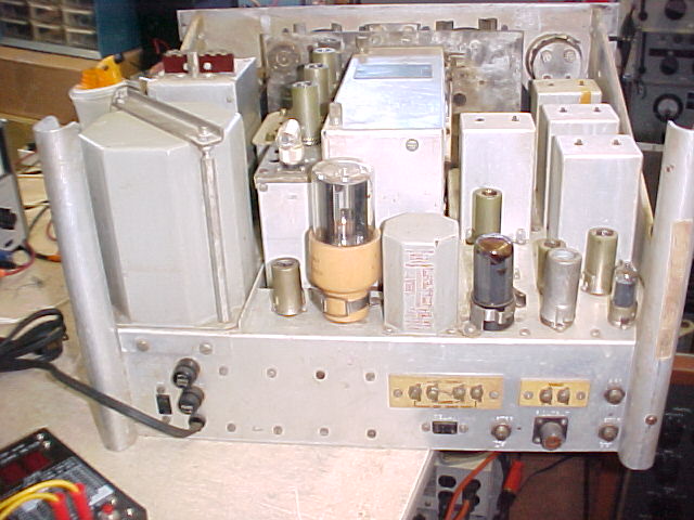
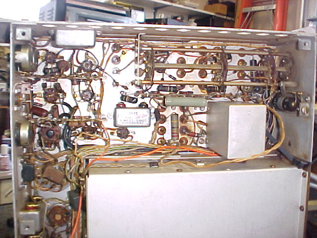
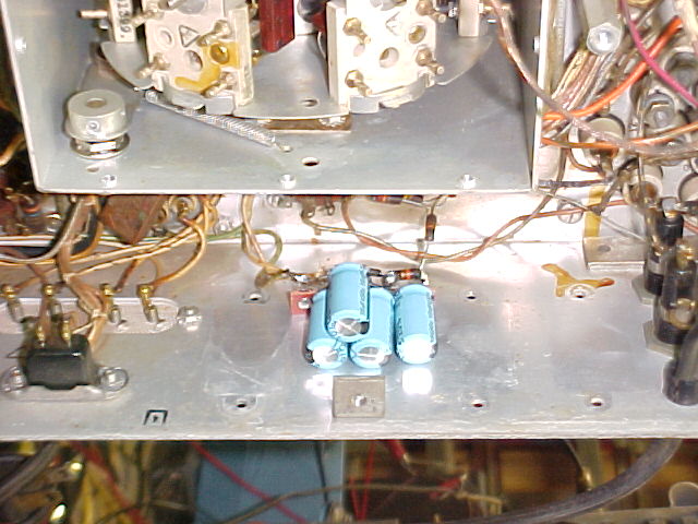
dial lamps and 6vac & meter wiring
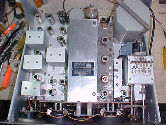
completed top view, before installing the cover
LOGGING CHART if no "err" is noted, the
dial is 1/2 or less of a pointer width off
a number in the error col. indicates how many pointer widths the reading is off.
| Frequency |
Log setting |
err | Frequency | Log setting | err | Frequency |
Log setting |
err |
| 0.650 | 122 | 8.500 | 109.4 | 31.000 | 114.5 | |||
| 0.900 | 317.5 | 10.000 | 234.9 | 39.000 | 284.5 | 3 | ||
| 1.200 | 401.1 | 11.000 | 318.4 | 45.000 | 406.3 | 1 | ||
| 1.500 | 70.9 | 14.000 | 531.3 | 50.000 | 503.4 | |||
| 2.500 | 375 | 16.000 | 63.6 | 52.000 | 542.2 | |||
| 3.100 | 510.2 | 20.000 | 226.5 | 1 | ||||
| 4.000 | 111.1 | 22.500 | 325.6 | |||||
| 5.500 | 337.8 | 26.000 | 457.4 | 2 | ||||
| 7.000 | 532.2 | 28.5000 | 543.7 |
Radio to see home page
comments to anchor@ec.rr.com
And remember: "They don't make tubes nowadays like they used to..."