
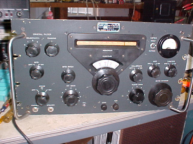
R-388, s/n 495 arrived 2/5/05
General observations upon initial survey:
MFP date Nov. 1952. Has top and bottom covers (has hex
nuts, not wing nuts to hold top cover), generally dirty, front panel is black
wrinkle, with silk screened lettering, some small chips & corrosion
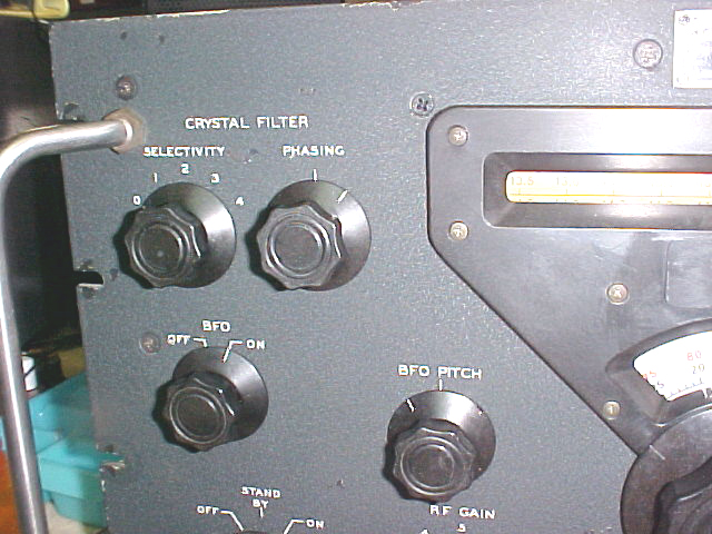
spots. "normal" scratches at rack mount slots. All knobs
original and no chips obvious. Some white index lines are worn, can be
re-filled. KC dial has scratches thru the translucent white background in
several places. The band dial drum is very yellowed and mottled, several
small scratches and marks, not too bad overall. If it will lighten up with
mild/gentle cleaning it should be OK. Side panels have some pitting and
rust, particularly on the outsides where scratched when sliding into cabinet or
rack. There is a roller at the back lower corner of each side panel.
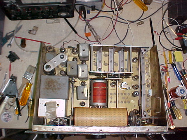
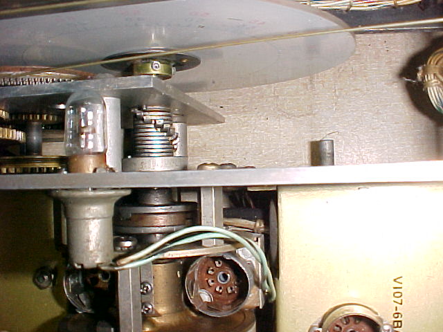
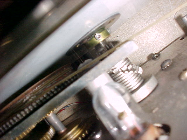
Only 4 tube shields in place, does have hold-downs for rectifier & filter, and for calib. xtal. The filter cap, 2x 35 mf @ 450v, checks out with ESR = 0.5 ohms for each section, good. Chassis top is grimy, should clean up well. 70E-15 PTO, s/n M11836CR, with "extra" tag "MI 00129-3511" Gear trains dirty but look OK, racks are free. Band indicator cord is broken. Slotted head mach. screws in place of soc. hd setscrews on phasing shaft coupler.
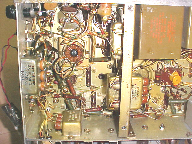
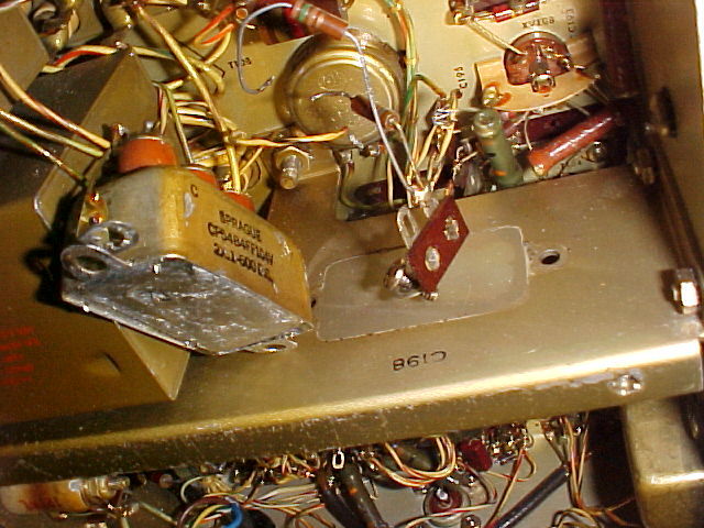
Under chassis is also dirty/grimy, maybe some cobwebs Especially grungy at rear rt corner at bandswitch - some crud on back panel there, if bottom panel hadn't been so clean inside I'd suspect a small previous rodent nest. Only one evidence of previous solder iron application, at C-198, to a terminal strip, a 150 ohm resistor has been bridged over the existing 150 ohm res, R-163, in the S-meter ckt - somebody wanted a more generous S-mtr ;-). Has a 3-wire AC-line cord, but the ground pin on the plug has been broken off.

Powered up with variac at abt 90% since the owner had had it powered up last week. Could hear calibrator faintly on several bands for about a minute, then it faded away to nothing. There was a light smell of a warm component near the front right of the panel, but nothing noticed underneath. Could still hear low level audio, which did change when BFO switched on, but no change with AVC on/off. The Selectivity Switch is noisy, particularly in the "0" posn. T-105 can is loose, something inside contacts it when moved, causes change in audio level. Powered off for a while then tried again, still faded away after a minute or so. BFO is off freq. Did determine that the PTO is off about 9kc end-to-end, probably too much for the normal adjustment..
Checked some tubes in the RF & IF secns, the 2 6AK5's in 1st RF & xtal osc. both checked weak to fair, 2 6BE6's ckd good, one very weak (1st mixer, int. mix., mix) replaced the poor one. 5 6BA6's ckd, all good, but one had very dirty pins & the filament didn't make contact at first in the tester. Still fades away after being on about 2 minutes; checked the 6AQ5 audio output tube, it had 1100gm vs 4100 spec. Now much more audio & it stays on. Can hear the calib. sig on all bands, tho' very weak on some. IIRC, the 6AQ5 in some Collins radios runs very hot, possibly there's a bias or screen voltage problem there that's making it run extra hot & maybe caused the hot smell. I'll check the grid coupling cap, the screen line doesn't have a dropping res. from the 210v line, and there's no cathode res.
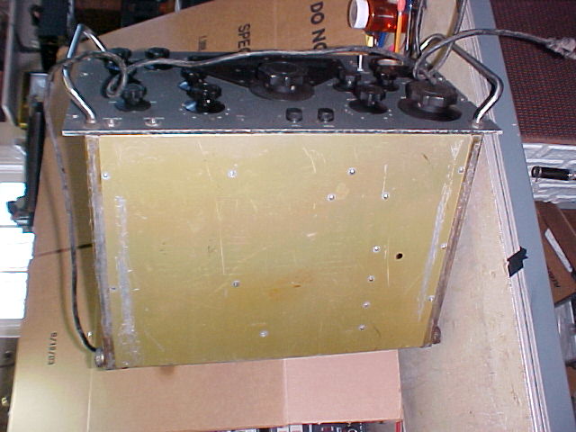
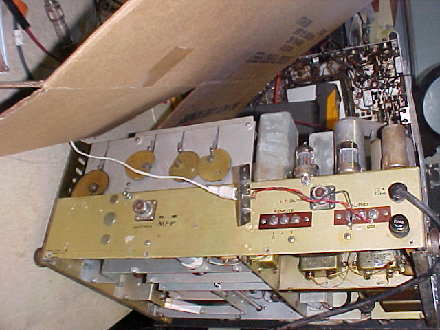
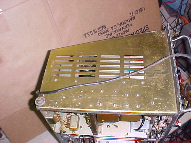
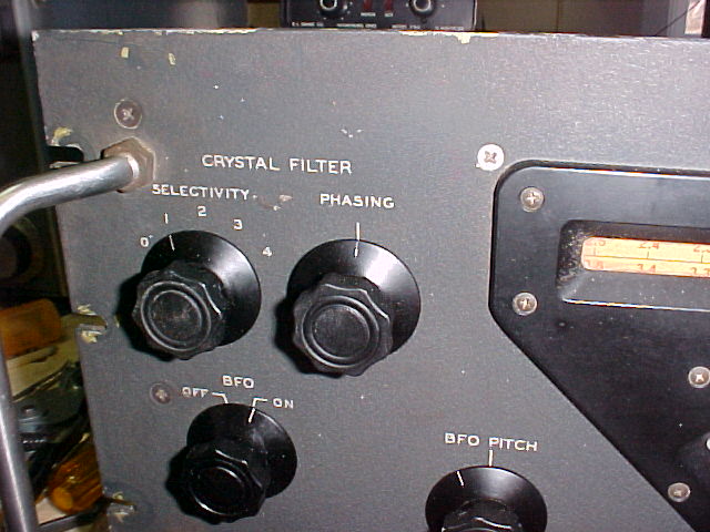
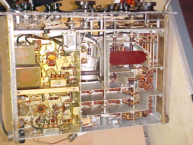
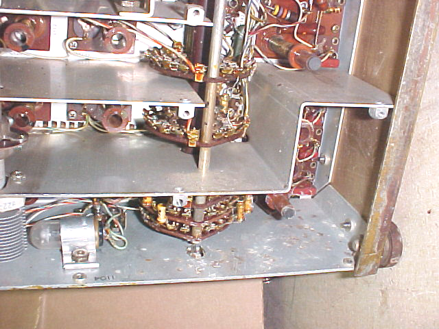
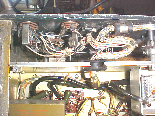
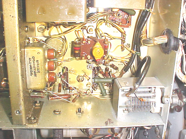
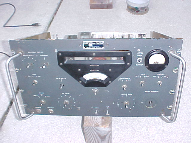
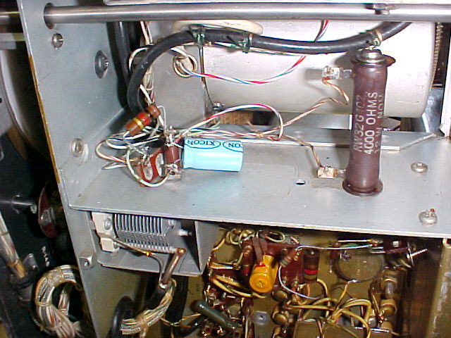
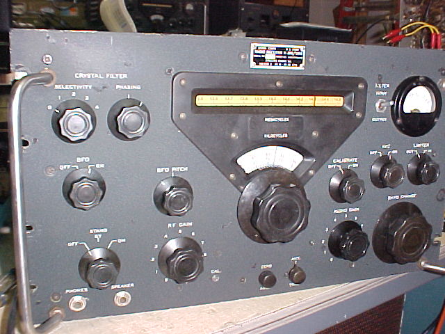
The top 2 pix are before cleaning, bottom 4 are after.
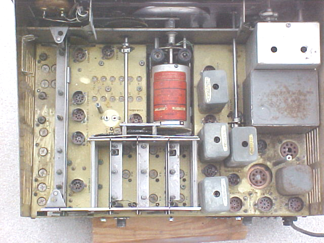
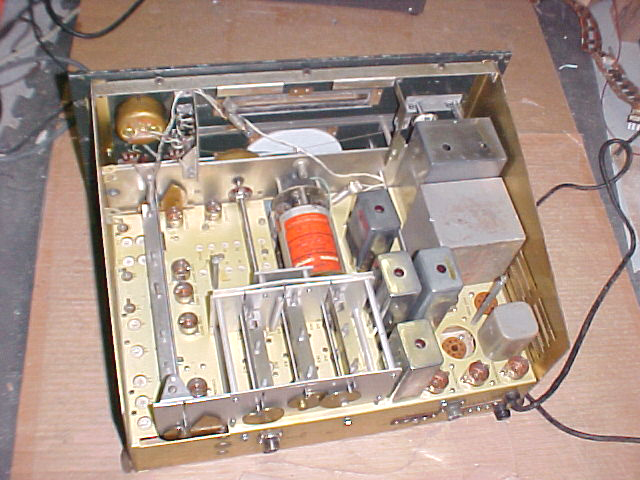
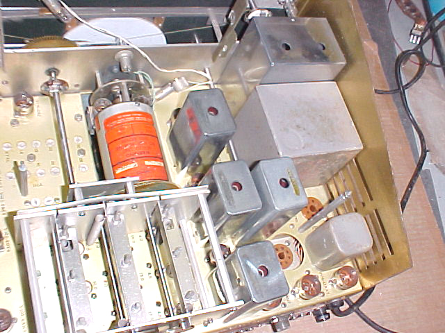
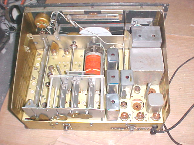
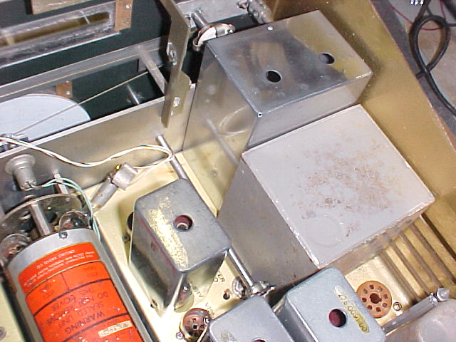
Quite a difference in the general level of crud. The 4 IF cans have been polished, as has the xtal phasing can. The light on them is deceptive, but they are not uniformly shiny, there are areas of tarnishing due to the stretching of the metal when formed, and subsequent stress corrosion. They are much nicer than as seen in the "before" shot - notice the reflections.
Tubes have been replaced, using DeOxit on all pins, the receiver is operable, but I did find the source of the hot smell/smoke. R-174, a 1K, 2watt dropping resistor in the B+ line to xtal osc, and 1st & intermed. mixers was overheating after power is on for over a minute. There's an 8mf@350vdc, C-223, right after the resistor which had an ESR of 4.0, not terrible, but it was leaky enough to put a 45 volt drop across the resistor (which actually measured 430ohms). This was a 4.5 watt load on the resistor, enough to drop the B+ to 170v vs normal 225v after the resistor & capacitor were replaced.
Alignment of the variable IF's and RF has been done, some more alignment and troubleshooting remains, but the following
has been done:
Bathtub caps are suspect and
all checked.
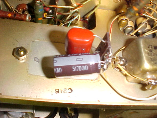
C-215, 20mf@150v had
ESR=2.0, bad, vs a good value of 0.25 for it's replacement. This is the
cath. bypass for V-109, AVC amp, possibly one reason there's little AVC action
and no S-meter deflection. It has been replaced by re-stuffing the
bathtub.
C-216, 20mf@150v is OK, ESR+
0.25. This is the bias filter for V-113, AF output. It has not been
replaced. (but was later, on a terminal strip with C-205A)

C-215 & C-216 in place
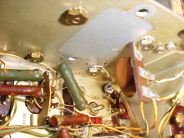
C-198A&B, 0.1mf @600v measured 4-5 megohms on the
Fluke, but less than 2 meg at 250v on the megger. They have been replaced
by re-stuffing the bathtub.
C-205A,B&C 0.1@600v
measured abt 1meg on the Fluke, but all better than 10megs @500v with the megger,
they do not need to be replaced. (but were, with discrete components on a
terminal strip)
details of "restuffing" C-198
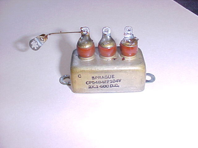
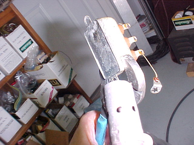
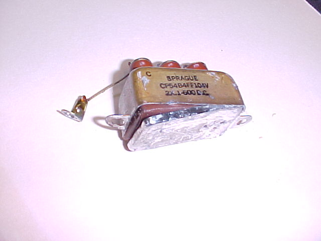

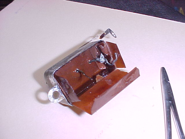
I think they are pretty much self explanatory, the only thing needing clarification
might be the use of a propane torch to heat up the joint to melt the solder.
With a normal "Bernzomatic" size torch, it only takes a few seconds to
do the job, the material is thin. I held the whole thing with channelocks
& rapped it on the concrete floor to knock the solder out. 2 out of 3
didn't need any re-heat to be able to pop the cover out. No black
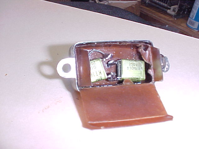
uckumpucky in there, but some oil in some, so it's easy. I had to use 2ea. 0.047
film caps in parallel for each section due to space restrictions not allowing
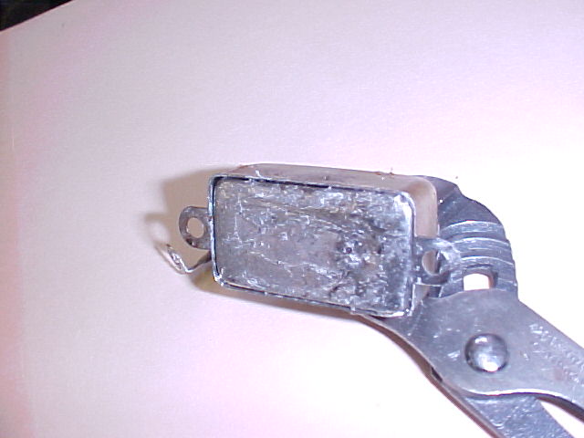
the singles I had on hand. The last pic is of it ready to go back in
place. I didn't re-stuff all bathtubs in this rcvr.
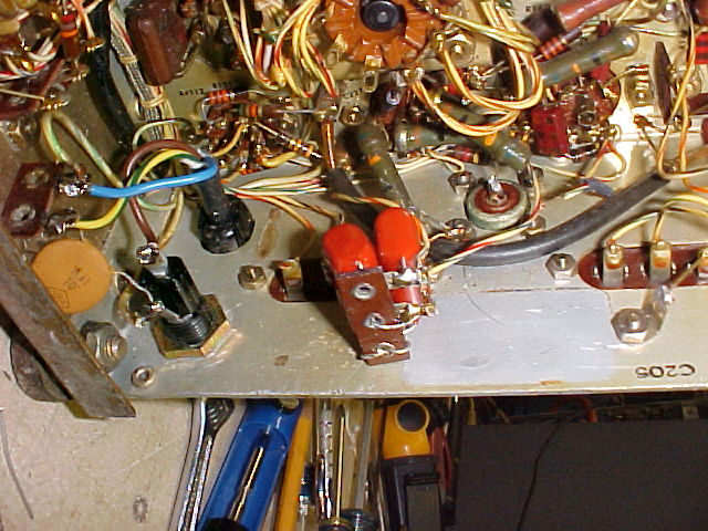
C-205A
& C-216
C-205B&C
C-214A&B
The S-meter problem is fixed, I first noticed a wire hanging off the switch, then
found the switch not working in that posn. Shot some DeOxit into it & worked it a lot, it seems solid now, don't know how long it'll last.
Switches without gold contacts don't do well in hi-impedance AGC/S-meter ckts, same problem with SP-600's. Not enuf current to keep them clean.
After 50 yrs or so it catches up to them ;-)
It's all working pretty well now, with the changes made
today. I may be close to done.
One problem
that I haven't heard anyone solve - there's an offset in freq. between odd
& even no. bands. You have to set the dial line one way this one's a
bit more than I've seen on others, good thing the PTO came in within 1 kc end to
end. I'll set the dial so it's about the same distance from straight up
and down for each band.
I will continue to
investigate this problem.
I thought about the offset problem, looking at the manual & block diagrams. Odd numbered bands use one variable IF, and evens use the other, they are separated by 1000kc at their midpoints. The signal then goes thru a mixer to the 500kc IF. I found that the BFO and 500kc IF were about 4kc off. I had centered the BFO on the IF freq. by "earholing" (not eyeballing), earlier, before I had checked the actual freq. This seems to have fixed (at least greatly improved) the offset problem, it was about 10kc, now about 4.
I have filled in most of the nicks/scrapes on the front panel with flat black "engine black" model train paint, which matches the St. James quite well. "Before" on the left, "After" on the right. The flash lighting makes the painted spots stand out more than they actually appear. They are visible, but I think it's a lot nicer than it was before.
I'm about
done with this one. Tom, why don't you come pick it up? ;-)
To see some of my other work on Collins equipment, with the PTO work in
detail,
click HERE and HERE
and HERE
Radio to see home page
comments to anchor@ec.rr.com
And remember: "They don't make tubes nowadays like they used to..."