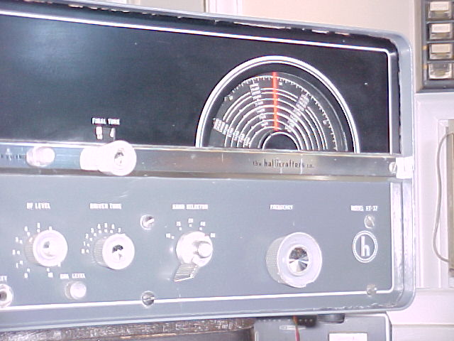
Hallicrafters HT-37
I bought this as a project, as I wanted to, and have, compare both construction and operation with my HT-32. It operates very much the same as the HT-32, as the basic difference is in the sideband generation method. The HT-37 with it's phasing type sideband generation is known for good audio, but the HT-32 gets good reports also. They both have a pair of 6146's as finals, and power output is the same.
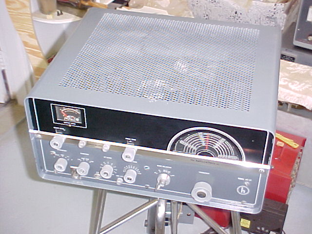
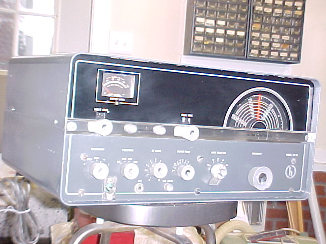
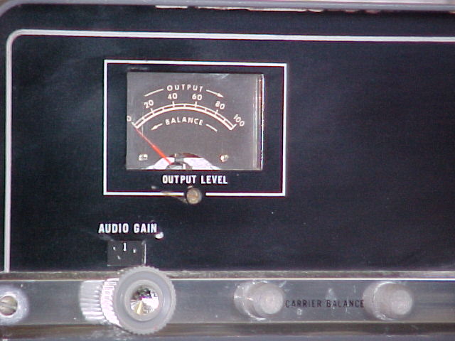
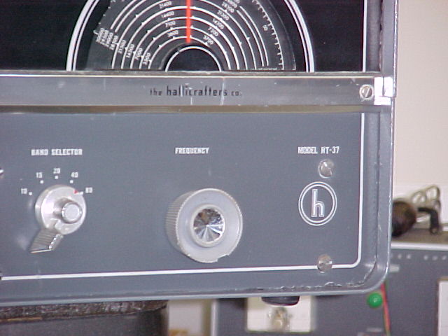
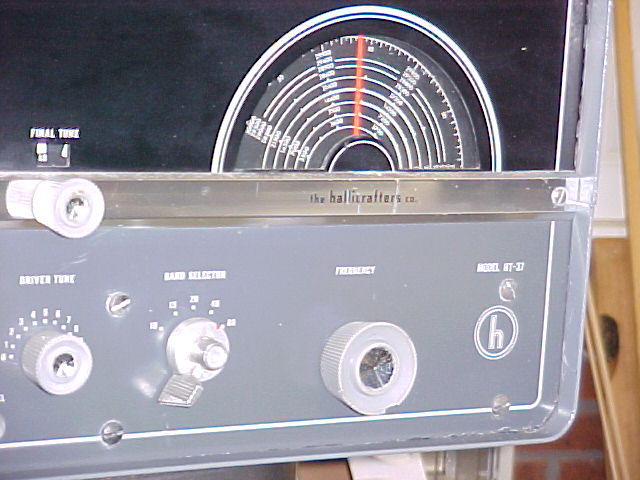
The chassis isn't beautiful, as it has the slightly rusty/tarnished appearance that is typical of old steel chassis. The front panel is good, the cabinet has been oversprayed, and knicked/flaked areas of the original paint is still noticeable. It could be stripped and repainted to look very good. But it is a good "user", which is what I wanted.
I wish I had the space to be able to set it up next to the HT-32 and switch between them for quick comparisons on the air. See below for some observations:

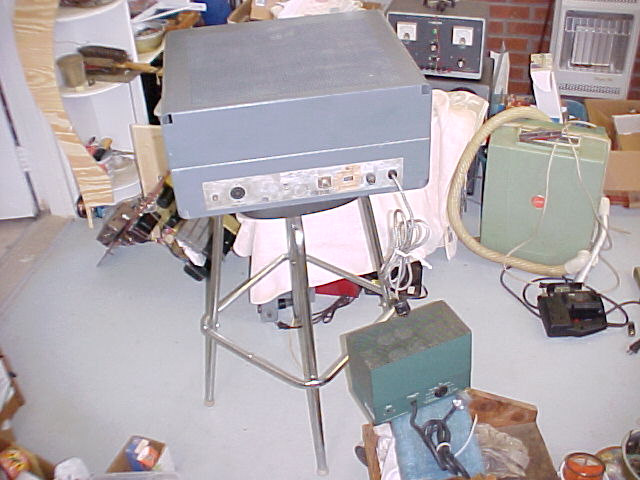
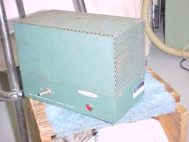
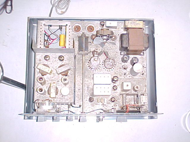
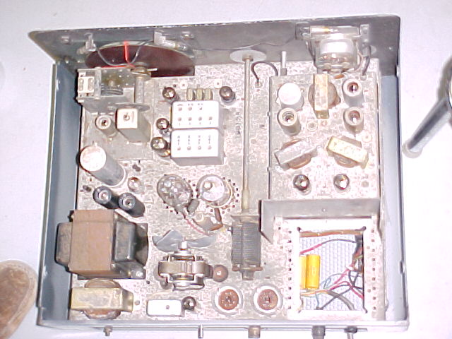
The following pix show it as it was after I had converted it to use a Heath HP-23 power supply. The power xfmr in the HT-37 had failed after I had been working on & using it for several weeks. The conversion to the Heath supply was reasonably easy, and worked very well. Other people have done the same thing to many similar boatanchor transmitters that have had transformer failures. I have since re-installed an original HT-37 power transformer.

================
I have recd several comments and questions after my HT-37 saga notes were sent to the Hallicrafters email reflector, basically in 2 areas, "how's the comparison to the HT-32?", and, "what about the SS'ing of the p.s.? This is a response to the list, for the benefit (?) of all.
I thought maybe my experiences of a week in April, 2002
would be of some interest:
I got an HT-37 abt 2 yrs ago to compare with my HT-32,
performance & audio quality wise, etc. Shortly after I got it cleaned
up, aligned, etc, the pwr xfmr did the common thing, HV winding shorted to filament
& to ground.
So, I put a Heath HP-23 on the end of an umbilical cord. It worked real
slick. After
doing it I discovered I'm not the first to do it. I made it easily
reversible, just in case I came upon a good xfmr, or sold it to someone who
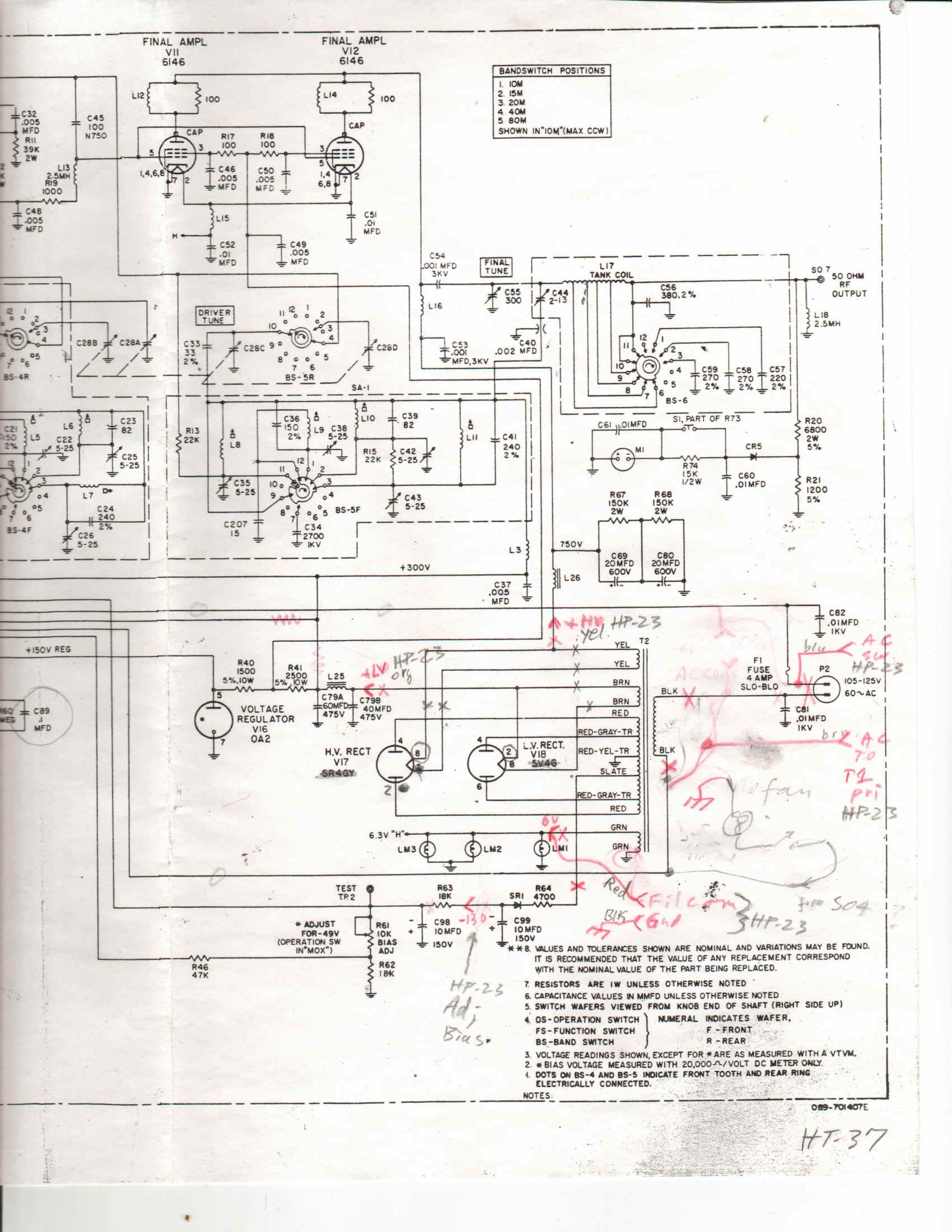
doesn't like mods. See the marked up schematic above for the circuit
changes. Well, the good xfmr arrived last week, and in it went.
The following is an account of it from there on, sent to a few friends---
Wed.PM I said:
"Just abt to finish up SS'ing the HT-37 p.s. after replacing the pwr xfmr,
per Lynn's recommendation. The xfmr I got looks practically new, I put a
60w bulb under it overnite & then also left it at abt 50vac for a few hrs
without rectifiers, so hopefully I've driven any moisture out & it'll live a
long time without the 2 5v fil. leads hooked to anything."
then, Thurs. noon:
" I had mentioned in my earlier message that I was abt to
fire up the HT-37 w/new xfmr, which I had really babied. Well, I tried.
It produced HV & LV at half AC input, but when I turned it up to abt 80v it
blew the fuse. To make a story shorter, it appears to have a short in the
primary, it's abt 0.7 ohms, I'd expect several ohms. No indication on the
20meg scale of anything to gnd or any other winding. It draws 3-4 amps at
<20vac in, I finally rigged up an ammeter with the variac. I was
disconnecting leads a bit ago when the xyl came home with the groceries, so I
did the unloading bit, planning to get back to the xfmr after lunch. Maybe
it'll be repairable, hope-hope."
Then Thurs late PM:
"Hi Guys,
Well, "don't jump to conclusions" is the lesson
learned. The transformer's OK, but it took a while & effort to decide
so. I ckd & re-ckd it & the p.s. ckt, etc, b4 removing it.
All looked OK, but still expected the primary was the trouble. Turned out
one of the diodes in the HV ckt had gone out. I had 2 in series for each
leg, the other one in that leg didn't go bad, so all the ckg didn't show it
shorted. Don't know why the other 1 in the leg didn't short. I
didn't figure it out until after I had removed the xfmr, pulled it's bells off
& looked. I checked it with a megger. No windings showed
anything between others or gnd. Then hooked it up to the variac.
Didn't pull any pri. current, HV came up OK, etc. Put 3 diodes in series
just to be sure, and put it all back together again. Seems like I do
things twice on a lotta stuff.
Now I just gotta find out why nothing else happens after the
relay clicks in. Got this far b4 supper, then went to radio club meeting
tonite. Maybe tomorrow.
At least I'm relieved it's not the xfmr, just a 10 cent
diode, even if I should have figured it out b4 doing 2 hrs work."
Fri. PM it all came together. The problem was a dirty
bandswitch & the bias voltage needed to be reset after the new p.s. work.
I put it on the air and made a few QSO's. It puts out 100+w on all bands.
I'm happy now, 73,
===============
How do they compare?
1. On the audio quality, I'll just say that's it's in the
ear of the beholder. The operator can't hear what's going out, only the
receiving operator can. I haven't operated the 2 xmtrs side by side so I
could put them both on the air at the same time, with the same microphone.
That would be the best way, if the rcvg op had good ears (I don't). I have
gotten good reports on both rigs. The phasing system of the HT-37 is
"supposed" to be better, many op's know that, and if they know that's
what they're hearing, their opinion may be tainted. Nobody's said the
HT-37 didn't sound good, similarly, I get very good reports for my CE 20A, also
a phasing rig. Maybe some day I can put both on the air at the same time
and get some real comparative opinions, particularly if I don't say which is on
at which time ;-)
2 Physically and electrically? There are
very few electrical differences beyond the SB generation. Even
mechanically the chassis layout is pretty much the same, it might even be
possible to swap SB generators from one to the other without too much trouble
(neglecting the panel controls). But the external cabinetry, panel, &
knobs of the HT-37 show the cost saving that was a main feature of the HT-37.
It is definitely less solid, more flexible, and to me not as attractive.
When my daughter, married, not living with us, first saw my refurbished
HT-32/SX-101 station, her immediate reaction was, "aren't those beautiful
radios?" I doubt that she'd have the same reaction to the HT-37, it
is definitely a boatanchor, and attractive, but ---? I think the SX-101 is
the prettiest receiver made.
3. VFO Some HT-37, and I think HT-32,
vfo's take a long time to stabilize. My HT-32 doesn't, it doesn't move any
more than about 150cy from 1 min. after turn-on for as long as you care to wait.
I can't say the same for the HT-37, tho' I haven't put a freq. ctr on it like I
have the HT-32. The HT-37 does drift some for at least an hour. I
don't think there is any difference in the construction or components, but
haven't examined closely, maybe some one else can fill us in.
"Solid Stating" the pwr supply?
The HT-32/37 pwr xfmr is a "high failure rate" item, and the extra
line voltage and the resultant extra internal heat are probably the main reason,
made worse by moisture, if the unit's not been used for a long time. They
usually develop leakage or shorts, between the HV winding, a 5v winding, and
ground. It's happened in 2 HT-3x xmtrs, an SX-28, SX-101, and SX-42 of
mine. Replacement of the rectifiers with solid state items is one way of
reducing the heat. That will raise the DC voltage a bit, but that's not
too much of a concern in these transmitters, tho' isn't a good idea in some
rcvrs unless some means of reducing the B+ voltage is used.
A 6v fil. xfmr is often used as a bucking xfmr in the
120vac input to reduce the input voltage to closer to the original than what we
get nowadays. This could be done for most of our boatanchors, with or
without the SS'ing of the p.s. to provide protection from general overheating
& over voltage in the B+ areas.
I don't know of any problem going SS on the rectifiers
in a transmitter. It reduces transformer & general heat, which is a
great help in the HT-32/37. Disconnect the 2 5v fil. windings completely.
I haven't done it in the HT-32 that I have with the Peter Dahl xfmr, but have in
the HT-37. I use 2 1000piv diodes in series for the LV section, and 3 in
series for the HV section. I have used surge protection resistors of 5 to
20 ohms in the series strings, but this may be overkill.
I hope this answers some questions, and it may promote some
more opinions.
73, Al, W8UT
MORE INFO ON SOLID STATING THE HT-37
This is "quick and dirty," some stuff I sent to another ham in Dec. '02. For the sake of my time, I'll just paste in my msgs & some pix.
Hi Jack,
I just put some of my past HT-37 info together on my website.
I had put
some there a while ago, but cleaned it up a bit now. It's not linked to
the
home page yet so you have to use the following to get to it:
http://www.thecompendium.net/radio/HT37.htm
I thought you might be interested in it, particularly
the notes on SS
rectifiers.
73,
Al, W8UT
-------------------
Hi Jack,
No, you can't put the filaments in parallel. The
filament of each
rectifier is at it's HV potential, and they're different. You'd need 2
xfmrs, and they'd have to have HV insulation, probably most 5v xfmrs do,
'cuz they're mostly used for that application.
Solid stating HT-32's & '37's is not going to be
criticised by anyone,
particularly if they've ever lost one of those xfmrs. The best thing to do
is to completely remove the filament leads from the tube sockets to remove
the HV from those windings. That, plus the reduced heat generation in the
xfmr is the best thing for them.
I've lost one in an HT-37, after I had babied it &
thought it woud be
OK, and my HT-32 had lost it's b4 I got it, but hadn't been replaced yet.
The guy had bought a Peter Dahl, which was incl in the deal, about free.
I hope this is some help. Do you ever get one of the
HT-37's on the
Vintage SB net on Sun's? 14.293, 3PM ET, after the Halli net is done.
I'm
usually there, been using a CE 20A lately. (+amp)
73,
Al, W8UT
----------------
Hi Jack,
Give me another day or 2 & I'll take some pix of mine, or
draw a sketch,
or something, for you. Mounting in a tube base is the "nicest
way" but then
unless you disconnect the filament wires underneath, you still have HV on
those windings, which isn't really a problem, just reduces the danger of a
problem in the xfmr.
73,
Al
----------------
hi Jack,
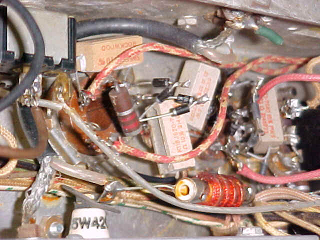
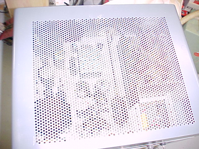
I finally got a round tuit. Take a look at these & see if
it makes any
sense. I used abt 20 ohm 5w resistors, they're not really necessary.
73,

-----------------
Hi Jack,
They are 1N4007's, 1amp, 1000piv. It's hardly worth
buying anything
less than that, you only save a few pennies on each I think, and you don't
have to remember/worry about what you've got. I was hasty when I sent my
last note w/skem, I should have said that the same applies for each
rectifier, but you probably figured that, particularly looking at the pix.
My HT-37 is really butt ugly, I'm surprized how bad every
time I look in
it. The chassis is very corroded/gray, it came from FL, the humid
environment I guess did it. Probably took a good dose of DeOxit, I don't
remember. But the panel is pretty good, & I gave the covers a quick
paint
spray to at least fill in the flakes. So my work in it probably reflects
that opinion, and doesn't enhance it any - just quick & dirty work. I
disconnected the filament lines & put a pc of shrink tube on the ends, so at
least it's reversible if anyone should ever want to take the trouble - why I
don't know. But the tube sockets must not have a tube plugged in when
using
vacant pins as terminals.
It is possible to just mount the diodes in a tube base &
plug it in,
leaving the filament leads in place, but as I said b4, that leaves HV on the
fil. winding as a possible failure point in the xfmr.
Another thing to watch when you're moving it in/out of the
bottom case,
the HV choke can easily get driven into that lip on the back of the case.
Mine was torn up when I got it but I was lucky enuf to separate the wires of
the last layer of winding & put some coil dope on them.
Keep me posted on your progress. Have a good holiday(s).
73,
Al
email to: anchor@ec.rr.com
----------------------
Here's an article that was in the May, 1964 issue of 73
magazine on adding Push to Talk
click on the thumbnails for full
size, then you can save & print if wanted.
-----------------
Radio to go to HOME
comments to anchor@ec.rr.com
And remember: "They don't make tubes nowadays like they used to..."
This page last updated on 02/11/2004.